

اینجاست که تمام کارها برای خواندن تفسیر مقادیر از سروو و سنسور انجام می شود. اگر خوانش ها نامنظم باشد، اشکال خوبی نخواهید داشت. همچنین اگر به سیگنال ها زمان کافی برای ارسال مجدد ندهید، خوانش فاصله نادرست دریافت خواهید کرد. بنابراین این کد فقط به اندازه کد آردوینو و تنظیمات حسگر شما خوب است.
چند شب طول کشید تا این کار را انجام دهم تا آنطور که میخواستم برسم، سختترین کار مربوط به مثلثات است که آنقدرها هم سخت نیست، بقیه چیزها توسط حلقهها و چند دستور IF انجام میشود. من از حلقههای FOR زیاد استفاده میکنم، زیرا همه عناصر را میتوان به صورت برنامهنویسی بدون نیاز به نوشتن هر مستطیل، دایره و خط روی صفحه با دستور خاص خود نمایش داد.
اگر با Processing آشنایی ندارید، به Processing.org بروید . پردازش یک ابزار/IDE است که به شما امکان برنامهنویسی و کدنویسی گرافیک و انیمیشن را میدهد، استفاده از آن رایگان و بسیار قدرتمند است – بهترین بخش این است که با آردوینو در همان سبک کد C/C++ کار میکند و به ما اجازه میدهد دادهها را از آردوینو بگیریم. و هر چیزی که به آن وصل است و سپس آن را روی صفحه تجسم کنید، مثلاً مانند صفحه رادار.
ابتدا باید متغیرها، پسزمینه و بارگذاری خود را در کتابخانههای پورت سریال تنظیم کنیم تا مطمئن شویم که میتوانیم دادههای ارسال شده توسط آردوینو را بخوانیم. همچنین باید تابعی از کتابخانه سریال به نام serialEvent() قرار دهیم که به داده های ارسالی گوش می دهد و به ما امکان می دهد داده ها را به راحتی بخوانیم. ما چند کار رشته آسان انجام می دهیم، خطوط پورت سریال را برای بدست آوردن موقعیت سروو و مقدار سنسور تقسیم می کنیم.
همچنین می توانیم صفحه رادار، رسم متن، اندازه گیری ها و شبکه نمایش را تنظیم کنیم. با پردازش چه چیزی نزدیکترین است، بالای تابع draw() ابتدا با هر چیزی که بعداً در بالای آن ترسیم میشود، نمایش داده میشود. بنابراین خطوط و متن ما در پایین تابع خواهد بود بنابراین همیشه قابل مشاهده خواهد بود. برای رسم خطوط و اندازه گیری ها از یک حلقه FOR استفاده می کنیم. تابع draw () یک فریم میکشد، بنابراین ما اساساً فریم را 180 بار دوباره ترسیم میکنیم - از چند آرایه برای ذخیره مقادیر قبلی استفاده میکنیم تا پیوسته به نظر برسد.
اکنون که آنها را داریم، میتوانیم شروع به نمایش مقادیر روی صفحه کنیم. ما از یک حلقه FOR برای حلقه زدن از طریق هر آیتم در آرایه، newValue و oldValue خود استفاده می کنیم. اینها به گونهای تنظیم شدهاند که 181 آیتم را در خود نگه دارند - 1 مورد در هر موقعیت سروو با 1 مورد اضافی در هر صورت، ما از طریق آنها حلقه میزنیم تا مرتباً قرائتهای قبلی را نمایش دهیم - اگر از خود موقعیت سروو برای تکرار در آرایه استفاده کنیم، هیچ داده قبلی وجود ندارد. نمایش داده شود زیرا موقعیت سروو همیشه در حال تغییر است.
اگرچه ما باید مختصات X و Y هر موقعیت سروو و قرائت فاصله سنسور را محاسبه کنیم. برای بدست آوردن این مقادیر از مثلثات با استفاده از سینوس و کسینوس و تبدیل موقعیت سروو به رادیان با استفاده از قرائت سنسور به عنوان فاصله از مرکز که نقطه را از آن رسم می کنیم استفاده می کنیم. برای کسب اطلاعات بیشتر در مورد این و برای نجات من از نوشتن آن، این آموزش را در Processing.org بررسی کنید .
طرح
زیر کدی است که برای ایجاد صفحه رادار استفاده می شود، دارای نظراتی برای کمک به توضیح است. هر چیزی که استفاده می شود یک تابع ساخته شده از زبان پردازش است و می توانید مرجع عملکردهایی را که من استفاده می کنم در بخش مرجع در وب سایت Processing.org پیدا کنید. بنابراین متدهایی مانند fill()، stroke()، rect()، line() و …
/*
luckylarry.co.uk
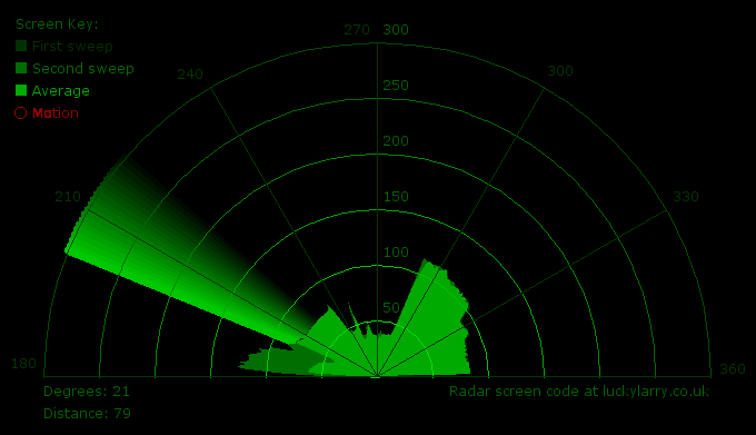
Radar Screen Visualisation for SRF-05
Maps out an area of what the SRF-05 sees from a top down view.
Takes and displays 2 readings, one left to right and one right to left.
Displays an average of the 2 readings
Displays motion alert if there is a large difference between the 2 values.
*/
import processing.serial.*; // import serial library
Serial myPort; // declare a serial port
float x, y; // variable to store x and y co-ordinates for vertices
int radius = 350; // set the radius of objects
int w = 300; // set an arbitary width value
int degree = 0; // servo position in degrees
int value = 0; // value from sensor
int motion = 0; // value to store which way the servo is panning
int[] newValue = new int[181]; // create an array to store each new sensor value for each servo position
int[] oldValue = new int[181]; // create an array to store the previous values.
PFont myFont; // setup fonts in Processing
int radarDist = 0; // set value to configure Radar distance labels
int firstRun = 0; // value to ignore triggering motion on the first 2 servo sweeps
/* create background and serial buffer */
void setup(){
// setup the background size, colour and font.
size(750, 450);
background (0); // 0 = black
myFont = createFont("verdana", 12);
textFont(myFont);
// setup the serial port and buffer
myPort = new Serial(this, Serial.list()[1], 9600);
myPort.bufferUntil('n');
}
/* draw the screen */
void draw(){
fill(0); // set the following shapes to be black
noStroke(); // set the following shapes to have no outline
ellipse(radius, radius, 750, 750); // draw a circle with a width/ height = 750 with its center position (x and y) set by the radius
rectMode(CENTER); // set the following rectangle to be drawn around its center
rect(350,402,800,100); // draw rectangle (x, y, width, height)
if (degree >= 179) { // if at the far right then set motion = 1/ true we're about to go right to left
motion = 1; // this changes the animation to run right to left
}
if (degree <= 1) { // if servo at 0 degrees then we're about to go left to right
motion = 0; // this sets the animation to run left to right
}
/* setup the radar sweep */
/*
We use trigonmetry to create points around a circle.
So the radius plus the cosine of the servo position converted to radians
Since radians 0 start at 90 degrees we add 180 to make it start from the left
Adding +1 (i) each time through the loops to move 1 degree matching the one degree of servo movement
cos is for the x left to right value and sin calculates the y value
since its a circle we plot our lines and vertices around the start point for everything will always be the center.
*/
strokeWeight(7); // set the thickness of the lines
if (motion == 0) { // if going left to right
for (int i = 0; i <= 20; i++) { // draw 20 lines with fading colour each 1 degree further round than the last
stroke(0, (10*i), 0); // set the stroke colour (Red, Green, Blue) base it on the the value of i
line(radius, radius, radius + cos(radians(degree+(180+i)))*w, radius + sin(radians(degree+(180+i)))*w); // line(start x, start y, end x, end y)
}
} else { // if going right to left
for (int i = 20; i >= 0; i--) { // draw 20 lines with fading colour
stroke(0,200-(10*i), 0); // using standard RGB values, each between 0 and 255
line(radius, radius, radius + cos(radians(degree+(180+i)))*w, radius + sin(radians(degree+(180+i)))*w);
}
برای جزئیات بیشتر: آردوینو + پردازش: یک صفحه رادار برای تجسم دادههای حسگر از SRF-05 بسازید - قسمت 2: تجسم دادهها
در ادامه، متن انگلیسی این مطلب را میتوانید مشاهده نمایید:
This is where all the work is done to read an interpret the values from the servo and the sensor. If the readings are to erratic then you won’t have nice shapes. Also if you don’t allow enough time to the signals to be sent back then you’ll get false distance readings. So this code is only as good as your Arduino code and sensor setup.
