

در این پست میخواهم پروژهای را برای شما شرح دهم که روی آن کار میکنم که شامل اتصال یک برد توسعه اندروید به یک (یا چند) برده آردوینو با استفاده از پروتکل modbus و rs485 است.
حتی با وجود اینکه ایده این پروژه میتواند در بسیاری از زمینهها اعمال شود، من ترجیح دادم آن را در یک زمینه خانه هوشمند معمولی تعریف کنم: یک صفحه نمایش لمسی که نورها را کم میکند، دما و وضعیت لامپها را نشان میدهد.
ویژگی خوب برد توسعه ای که من استفاده کردم این است که دارای رابط های زیادی مانند اترنت، rs485 ، rs232 و I²C است.
من صراحتاً rs485 را انتخاب کردم زیرا میکروکنترلرهای مبتنی بر آردوینو هنوز برای اترنت آماده نیستند (حتی اگر برخی از نمونهها هنوز وجود دارند اما موفقیت زیادی ندارند). در واقع، rs485 یک استاندارد شناخته شده است که به طور گسترده در زمینه صنعتی و در کاربردهای اتوماسیون ساختمان استفاده شده است. این یک اتوبوس نیمه دوبلکس، 2 سیم، کم نویز است که امکان اتصال با سرعت بالا و اتصال دستگاه های راه دور (تا 1200 متر) را فراهم می کند.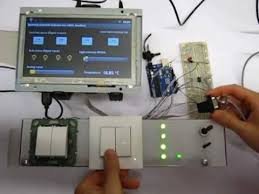
علاوه بر این، modbus یک پروتکل ارتباطی سریال است که برای کاربردهای صنعتی توسعه یافته است، باز و به راحتی قابل استقرار و نگهداری است. من از modbus RTU استفاده کردم ، اما تغییرات دیگری از پروتکل هنوز وجود دارد.
من پروژه را به بخش های اصلی تقسیم کردم، یعنی:
قطعات الکتریکی
عناصر اصلی این پروژه به شرح زیر است:
- یک پنل چند لمسی مبتنی بر اندروید
- یک (یا چند) برد آردوینو ( نه لزوما مگا)
- یک تراشه Maxim's Max485 (یا در نهایت یک تراشه ارزان تر مانند sn75176a TI )
- رهبری
- سنسور دما (مانند TMP36 )
- سوئیچ ها
- یک پتانسیومتر
- یک مقاومت 120 اهم (به دلیل فاصله کم master و slave در این پروژه استفاده نمی شود)
- سیم و مقداری تجربه لحیم کاری
مدار
تصویر سمت راست نمای کلی از نمودار مدار پروژه را نشان می دهد (برخی از قسمت های تصویر ساخته شده با فریتزینگ ). با این حال، بیش از یک برد آردوینو را می توان به اتوبوس متصل کرد.
طرح آردوینو
طرح آردوینو اساسا از کتابخانه SimpleSlaveModbus استفاده می کند ( آموزش نحوه نصب یک کتابخانه جدید آردوینو ). من شخصاً به شما پیشنهاد می کنم که نگاهی به مستندات بیندازید تا ایده بهتری در مورد نحوه کار این کتابخانه داشته باشید.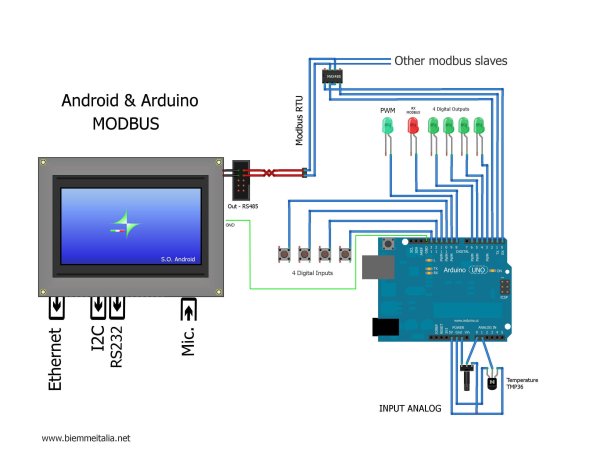
پس از گنجاندن هدر کتابخانه modbus در ابتدای کد منبع، یک آرایه عدد صحیح (به نام holdingRegs) را اعلام کردم که رجیسترهای modbus را ذخیره می کند. کد تابع 16 در آنها می نویسد در حالی که کد تابع 3 آنها را می خواند. دو رجیستر اول برای مقادیر آنالوگ مانند مقادیر جمعآوری شده از پینهای A0 و A1 آردوینو رزرو شدهاند. INDIG0 تا INDIG4 برای ورودی های دیجیتال، OUTD0 به OUTD4 برای خروجی های دیجیتال و AOUT0 برای PWM ارائه می شوند.
در بخش تنظیمات طرح، تابع modbus_configure را فراخوانی میکنم تا modbus را با پارامترهای زیر پیکربندی کنم: نرخ باود، شناسه برده (آدرس)، پین فعال کردن انتقال و تعداد رجیسترها. متعاقبا، من اساساً پین های دیجیتال آردوینو را با pinMode پیکربندی می کنم. در حلقه طرح، یک فراخوانی به modbus_update وارد کردم که به عنوان پارامتر اول، ارجاع به آرایهای را که رجیسترهای modbus را ذخیره میکند، مشخص میکند. این تابع از دستورات modbus دریافتی مراقبت می کند و در صورت نوشتن یا خواندن درخواست ها، رجیسترها را بر اساس آن اصلاح می کند.
برای جزئیات بیشتر: Android Arduino Communication از طریق Modbus و Rs485
در ادامه، متن انگلیسی این مطلب را میتوانید مشاهده نمایید:
In this post I’d like to describe you a project I’m working on that consists of connecting an Android development board to one (or more) Arduino slave(s) using modbus protocol and rs485.
Even though the idea of this project could be applied in many fields, I chose to contextualize it in a typical smart home context: a touch display that dims lights, shows temperatures and bulbs statuses.
The nice feature of the development board I used is that it has many interfaces such as Ethernet, rs485, rs232 and I²C as well.
I expressly selected rs485 because Arduino-based microcontrollers are not ready for Ethernet yet (even though some examples still exist but without great success). Indeed, rs485 is a well known standard that has been widely used in the industrial context and in building automation applications. It is a half-duplex, 2-wires, low noise bus that allows high speeds and remote devices connection (up to 1200 meters).
Furthermore, modbus is a serial communication protocol, developed for industrial applications, open and easy to deploy and maintain. I used modbus RTU, but other variations of the protocol still exist though.
I divided the project into core parts, namely:
Electrical parts
The key ingredients for this project are the following:
- An Android based multi touch panel
- One (or more) Arduino board (not necessarily Mega)
- A Maxim’s Max485 chip (or eventually a cheaper one like TI’s sn75176a)
- Led
- A temperature sensor (like TMP36)
- Switches
- A potentiometer
- One 120 Ohm resistor (not used in this project because of the short distance of master and slave)
- Wires and some soldering experience
Circuit diagram
The picture on the right shows an overview of the circuit diagram of the project (some parts of the picture made with Fritzing). More than one Arduino board could be connected to the bus though.
Arduino sketch
Arduino sketch essentially uses SimpleSlaveModbus library (Tutorial on how to install a new Arduino library). I personally suggest you to take a look at documentation in order to have a better idea on how this library works.
After including the modbus library header at the beginning of the source code,I declared an integer array (named holdingRegs) that stores the modbus registers. Function code 16 writes into them whereas function code 3 read them. The first two registers are reserved for analog values such as those gathered from A0 and A1 Arduino’s pins. INDIG0 to INDIG4 are served for digital inputs, OUTD0 to OUTD4 to digital outputs and AOUT0 for PWM.
In the setup section of the sketch, I call the modbus_configure function in order to configure the modbus with the following parameters: the baud rate, the ID of the slave (address), the transmit enable pin and the number of registers. Subsequently, I basically configure the digital Arduino pins with pinMode. In the loop of the sketch, I inserted a call to modbus_update specifying, as a first parameter, the reference to the array that stores the modbus registers. This function will take care of the received modbus commands and will modify the registers accordingly in case of writing or reading requests.
For more detail: Android Arduino Communication through Modbus and Rs485
