

به دنبال آموزش های اینجا ، من توانستم یک دوربین دیجیتال قدیمی را با استفاده از یک آردوینو، یک رله و یک برنامه نرم افزاری متن باز به نام makeAVI (ویندوز) به یک دوربین تایم لپس تبدیل کنم. برای اصلاح دوربین، پوشش دوربین را جدا کردم و دکمهای را که شاتر را فعال میکند، برداشتم.
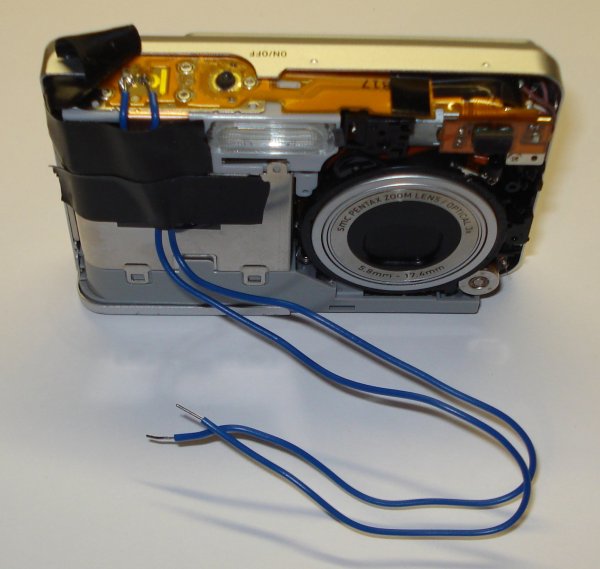
تشخیص از روی تصویر دشوار است، اما با فشار دادن دکمه شاتر، دو پایانه مسی به هم فشار میآورند و سیگنالی را برای گرفتن عکس به دوربین میفرستند. من به هر یک از پایانه های مسی یک سیم لحیم کردم. لمس انتهای آزاد هر یک از این سیم ها با هم معادل فشار دادن دکمه شاتر برای گرفتن عکس است. مرحله بعدی استفاده از یک رله معمولی باز (منبع از RadioShack) برای کنترل زمان فعال شدن شاتر بود.
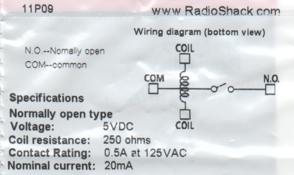
نمودار سیم کشی همراه با رله عملکرد رله را به خوبی تقطیر می کند. به زبان ساده، اثبات سیگنال 5 ولت به سیم پیچ، سوئیچ را می بندد. اگر یک سیم از شاتر به پین های "COM" و "NO" روی رله وصل شده باشد، با فعال کردن رله یک عکس می گیرد. در تصویر بالا سیم زرد از پایه آردوینو 7 به پین کویل روی رله متصل شده است. سیم سبز رنگ دیگر پین سیم پیچ رله را به زمین متصل می کند. هنگامی که آردوینو پین 7 HIGH را می سازد، رله بسته می شود و به دوربین می گوید که عکس بگیرد.
برای جزئیات بیشتر: دوربین دیجیتال تایم لپس با استفاده از آردوینو
در ادامه، متن انگلیسی این مطلب را میتوانید مشاهده نمایید:
Following the instructable here, I was able to turn an old digital camera into a time lapse camera using an arduino, a relay, and an open source software program called makeAVI (windows). To modify the camera I disassembled the camera cover and removed the button that activates the shutter.
It is difficult to tell from the picture, but pressing the shutter button pushes two copper terminals together sending a signal to the camera to take the picture. I soldered a wire to each of the copper terminals. Touching the free ends of each of these wires together is equivalent to pushing the shutter button to take a picture. The next step was to use a normally open relay (sourced from RadioShack) to control when the shutter was activated.
The wiring diagram included with the relay distills the operation of the relay quite nicely. In laymen terms, proving a 5V signal to the coil closes the switch. If a wire from the shutter is connected to the “COM” and “N.O.” pins on the relay then activating the relay takes a picture. In the picture above the yellow wire is connected from arduino pin 7 to a coil pin on the relay. The green wire connects the other relay coil pin to ground. When the arduino makes pin 7 HIGH, the relay closes and tells the camera to take a picture.
For more detail: Time Lapse Digital Camera using Arduino
