

اهداف
سلام به همگی.
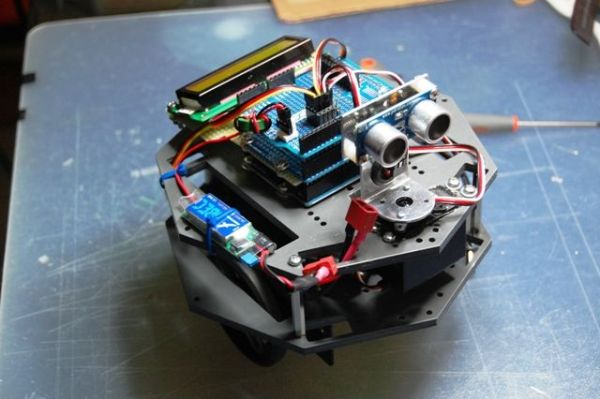
امیدوارم ربات کوچکی را که به تازگی ساخت آن را تمام کرده ام به اشتراک بگذارم.
بسیاری از Ping Boat وجود دارد، شاید با یک آموزش و نمایش کمتر بدون تظاهر، آنچه را که می توانم انجام دهم را نشان دهد.
من هدف خود را ساختن روباتی قرار دادم که از موانع اجتناب کند، از این رو از Ping استفاده کردم، که استقلال بیشتری داشت (و دردسر کمتری برای بارگذاری مجدد قلم همیشه) داشت و فاصله اندازه گیری شده مانع را روی نمایشگر LCD نمایش داد.
این آموزش برای مبتدیان اما با دانش الکترونیک و برنامه نویسی آردوینو طراحی شده است.
مرحله 1: فهرست مواد
1 – آردوینو UNO یا سازگار
2 – ماژول OCTAGON GioBlu Robotics http://www.gioblu.com/prodotti?page=shop.product_details&flypage=flypage_images.tpl&product_id=136&category_id=60 یا فریم دیگر
1 – پینگ مونت k)) Paracket http://www.parallax.com/Store/Robots/AllRobots/tabid/755/ProductID/248/List/0/Default.aspx?SortField=ProductName,ProductName
2 – سروو موتور با چرخش 360، در مورد من HSR- 1425SCR
2 – چرخ های 6 سانتی متری با لاستیکی بدون لغزش
1 – سروو std برای پینگ (در مورد من لازم نیست اما قابل اجرا است)
2 – براکت های سروو Gioblu Robotics http://www.gioblu.com/prodotti?page= shop.product_details&flypage=flypage.
tpl&product_id=78&category_id=34 4 – جداکننده PCB از 4 سانتی متر http://http://www.robot-italy.com/product_info.php?cPath=7_135&products_id=1189
2 – protoschield برای سرووها، باتری و نمایشگر و http://www.robot-italy.com/product_info اضافه شده است. php?products_id=879 (یا سایت های دیگر)
1 – 16×2 صفحه نمایش LCD سازگار با HD44780 http://www.robot-italy.com/product_info.php?cPath=59_194&products_id=237
1- پتانسیومتر
1 – نگهدارنده باتری 9 ولت
1 – 2s Lipo 1200mAh 7.4 v
1 – UBEC 5.4 / 6V http://www.cnchelicopter.com/servlet/the-1528/hobbywing-UBEC-dsh-3A-(2-dsh-6S-Lipo/Detail
1 – چرخ محوری
1 – تکه ای از تخته ماتریس برای محافظ صفحه نمایش
– مقداری نوار برای سپر
– مقداری پیچ صبر و اشتیاق..
مرحله 2: ساخت سپر SERVO
ابتدا با سپر شروع می کنیم، چرا این راه را انتخاب کرده ام؟ هنگامی که شما نیاز به اتصال چندین سروو موتور، سنسور، باتری و غیره دارید، البته، چندین سیگنال پین، منبع تغذیه و زمین برای استفاده وجود دارد.
معمولاً رباتهای کوچک مختلف توسط یک تخته نان به هم متصل میشوند تا به شما امکان مدیریت همه چیز را به هزینه رشتههای زیادی در اطراف بپردازید که شاید هر بار که اتصال را قطع میکنید و همچنان همیشه احساس هرج و مرج میکنید.
یک محافظ برای اتصال به آردوینو همه چیز را ساده می کند و باعث می شود اتصالات راحت تر شود. همانطور که می دانید برای سرووها یا موتورها در حال حاضر در بازار متفاوت و کاربردی وجود دارد، به عنوان مثال یک یا dell'Adafruit یا SparkFun، در هر صورت تحقق در خانه بسیار ساده و ارزان است.
همانطور که از دو عکس اول مشاهده می کنید چندین ردیف از سه پایه لحیم شده است (من 6 را ساخته ام، اما می توانید چندین پایه دیگر اضافه کنید)، هر پایه مربوط به سه قطب سروو و سنسور است ( سیگنال، 5v، gnd -سفید/قرمز/سیاه یا زرد/قرمز/پشت ). سپس به صورت موازی (عکس سوم) 5 ولت (پایه مرکزی) و GND (سیم آبی در تصویر) و دومی به کانکتور برق وصل شده است، بنابراین تمام پایه هایی که به ردیف پین ها وصل خواهید شد، با هم تغذیه می شوند.
برای پین سیگنال، میتوانید تصمیم بگیرید که آیا در ابتدا میدانستید (مثل مورد من) با کدام پایه مطابقت دارد، یک سیم را مستقیماً به پین مربوطه لحیم کنید، یا اگر میخواهید هر از گاهی آن را مدیریت کنید، فقط اضافه کنید (عکس دوم ) یک ردیف مادگی نواری برای اتصال با سیم به پین مورد نظر. در بالا یک دکمه تنظیم مجدد و یک LED متصل به پین 13 به طور مستقیم به برد آردوینو اضافه کردم.
مرحله 3: ساخت SHIELD LCD
البته نادیده گرفته می شود، زیرا ده ها آموزش در مورد نحوه اتصال یک نمایشگر به برد آردوینو پیدا خواهید کرد، به عنوان مثال
http://arduino.cc/en/Tutorial/LiquidCrystal
، اما تکرار می کنم، اگر می خواهید از فرصت استفاده کنید و وارد پروژه شوید. ، که لازم است تعداد سیم های اطراف را کاهش دهیم که در این مورد چندین سیم هستند، بنابراین می توانیم دوباره یک محافظ بسازیم که می تواند برای پروژه های دیگر با آردوینو مفید باشد .
از 16 پین یک نمایشگر، تنها 12 پایه برای هدف ما مورد نیاز است.
اگر به عکس اول و سوم نگاه کنید، باید تخته نان بردی را برش دهید که به خوبی به عنوان پشتیبان نمایشگر و مانند یک «پل» متصل به پینهای آردوینو باشد.
پس چه کار باید بکنیم (من برای بهتر خواندن نمایشگر، همانطور که در تصویر 2 نشان داده شده است، کمی مایل لحیم کرده ام) یک نوار مادگی 16 فوتی به تخته ماتریس، از هر پین استفاده شده بسازیم (جدول ها را ببینید) در زیر) سیمی که مستقیماً به پین مربوطه پروتوشیلد لحیم شده است، سپس روی برد آردوینو همپوشانی می کنیم و بالای این سپر (عکس آخر) سیمی را که برای سروو و سنسور با سیم قابل مشاهده صفر ساخته شده است، دریافت می کنیم .
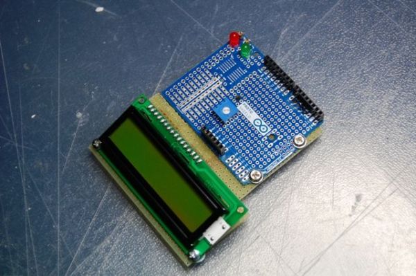
آخرین عکس صفحه نمایش در حال کار است.
مرحله 4: جدول برای اتصالات
| پین | اتصال به | |||||
| 1 | GND | |||||
| 2 | 5 ولت | |||||
| 3 | (پین مرکزی پات – یک سیم را به 5 ولت و یکی را به GND اضافه کنید) | |||||
| 4 (RS) | 3 | |||||
| 5 (RW) | GND | |||||
| 6 (EN) | 4 | |||||
| 11 (DB4) | 5 | |||||
| 12 (DB5) | 6 | |||||
| 13 (DB6) | 11 | |||||
| 14 (DB7) | 12 | |||||
| 15 | 5 ولت | |||||
| 16 | GND | |||||
| پین سیگنال سروو 10 | ||||||
| منجر به پین 13 شد | ||||||
| پین سیگنال سنسور پینگ 7 | ||||||
| پین چرخ DX 9 | ||||||
| SX Wheel sx Pin 8 | ||||||
قدرت نمایشگر را زیر سپر سروو قرار دهید تا با ظرفیت باتری مدیریت شود.
برای جزئیات بیشتر: ربات نمایش پینگ آردوینو من Goals Hello all. 1 – Arduino UNO or compatible First we begin by shield, why I have chosen this path?. When you need to connect several servo motors, a sensor, batteries etc, of course, there are several PIN signals, power supply and ground to use. As you can see from the first two photos are soldered several rows of three legs (I have made ââ6, but you can add several more), each leg corresponds to the three poles of the servo and the sensor (signal, 5v, gnd -white/red/black or yellow/red/back). Then sold in parallel (third photo) the 5v (center pin) and GND (pictured blue wire) and the latter connected to the power connector, so all you will connect to the row of pins will be powered together. Skipping of course, as you will find dozens of tutorials on how to connect one display to Arduino board eg Of the 16 pins of a display, only 12 are needed for our purpose. Put the display power under servo shield so it is managed by a battery’s capacity. For more detail: My Arduino Ping Display Robot
2 – ماژول OCTAGON GioBlu Robotics
1 – Ping))) کیت براکت نصب Parallax
2 – موتورهای سروو با چرخش 360، در مورد من HSR/1425SR-box ]
در ادامه، متن انگلیسی این مطلب را میتوانید مشاهده نمایید:
I hope to please share a little robot that I have just finished building.
There are many Ping Boat, perhaps with a tutorials and display less so without pretension, will illustrate what I could do.
I gave myself the goal of realizing a robot that avoids obstacles, hence the use of Ping, who had more autonomy (and less hassle to reload always stylus) and displayed on a LCD display the distance measured obstacle.
The tutorial is directed for beginners but with knowledge of electronics and Arduino programming.
Step 1: List of Materials
2 – Module OCTAGON GioBlu Robotics http://www.gioblu.com/prodotti?page=shop.product_details&flypage=flypage_images.tpl&product_id=136&category_id=60 or other frame
1 – Ping))) Parallax mounting bracket kit http://www.parallax.com/Store/Robots/AllRobots/tabid/755/ProductID/248/List/0/Default.aspx?SortField=ProductName,ProductName
2 – Servo motors with 360 rotation , in my case HSR-1425SCR
2 – 6 cm wheels with rubber no-slip
1 – std servo for the Ping (in my case is not required but can be implemented)
2 – servo brackets Gioblu Robotics http://www.gioblu.com/prodotti?page=shop.product_details&flypage=flypage.tpl&product_id=78&category_id=34
4 – PCB spacers from 4 cm http://http://www.robot-italy.com/product_info.php?cPath=7_135&products_id=1189
2 – protoschield for servos, battery and display and added http://www.robot-italy.com/product_info.php?products_id=879(or other sites)
1 – 16×2 HD44780 compatible LCD Display http://www.robot-italy.com/product_info.php?cPath=59_194&products_id=237
1- potentiometer
1 – 9v battery holder
1 – 2s Lipo 1200mAh 7.4 v
1 – UBEC 5.4 / 6V http://www.cnchelicopter.com/servlet/the-1528/hobbywing-UBEC-dsh-3A-(2-dsh-6S-Lipo/Detail
1 – pivot wheel
1 – piece of matrix board for the display shield
– some strip for shield
– some screw patience and passion..Step 2: SERVO SHIELD CONSTRUCTION
Normally the various little robots are joined by a breadboard to allow you to manage everything at the expense of a lot of threads around that maybe every time you disconnect and still always give a feeling of chaos.
A shield to be attached to Arduino simplifies everything and makes it more convenient connections. As you know for the servos or motors there are already on the market different and functional, eg one or dell’Adafruit or SparkFun, in any case the realization in the house is very simple and inexpensive.
For the signal pin, you can decide if you knew at the start (as in my case) corresponds to which pin, solder a wire directly to the corresponding pin, or if you want to manage it from time to time just add (second photo), a row of strip females to connect with a wire to the desired pin. In the above I added a reset button and a LED connected to pin 13 directly to Arduino board.Step 3: LCD SHIELD CONSTRUCTION
http://arduino.cc/en/Tutorial/LiquidCrystal
but I repeat, if you want to take the opportunity to enter into the project, which necessary to reduce the number of wires around that in this case are several, so we can again make a shield that can be useful for other projects with the Arduino.
If you look at the first and third photo should crop a breadboard that will serve us well as a support for the display, and like a “bridge” connecting to the Arduino pins.
So what should we do, sold (I have soldered slightly inclined, as shown in picture 2, in order to better read the display) a female strip of 16 feet to the matrix board, make from each pin that is used (see the tables below) a wire soldered directly to the corresponding pin of Protoshield, then we’re going to overlap to the Arduino board and above this shield (last photo) will get that one made for the servo and sensor with zero visible wires.
The last photo is the display in operation.Step 4: TABLE FOR THE CONNECTIONS
PIN
connect to
1
GND
2
5V
3
(Central Pin of the POT – Add to this one wire to 5v and one to GND)
4 (RS)
3
5 (RW)
GND
6 (EN)
4
11(DB4)
5
12(DB5)
6
13(DB6)
11
14(DB7)
12
15
5V
16
GND
Ping Servo Signal Pin 10
Led to Pin 13
Ping Sensor Signal Pin 7
DX Wheel Pin 9
SX Wheel sx Pin 8
2 – Module OCTAGON GioBlu Robotics
1 – Ping))) Parallax mounting bracket kit
2 – Servo motors with 360 rotation , in my case HSR-1425SCR
