

این مبحث نحوه ارتباط آردوینو با ساعت واقعی DS1307 برای ساخت ساعت و تقویم را نشان می دهد.
برای درک آسان پروژه و کد، باید دیتاشیت DS1307 را مطالعه کنید.
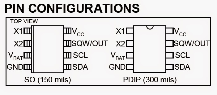
تخصیص پین DS1307:
تصویر از دیتاشیت ds1307 گرفته شده است و تخصیص پین تراشه RTC ما را نشان می دهد:
ساعت بیدرنگ آردوینو با استفاده از مدار DS1307:
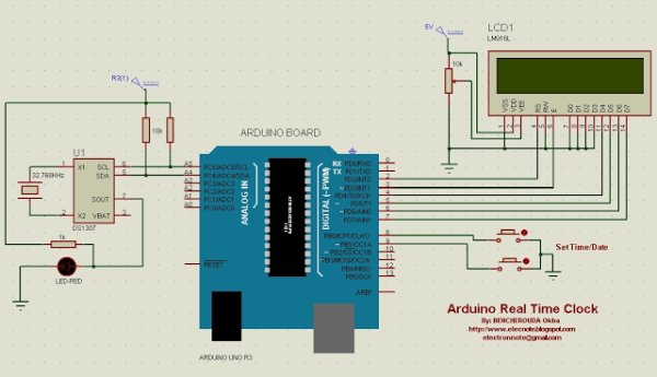
در شماتیک مدار دو دکمه برای تنظیم زمان و تاریخ وجود دارد.
نمایشگر LCD هم زمان و هم تاریخ را به طور همزمان نشان می دهد و LED متصل به ds1307 روشن و خاموش می شود (قابلیت برنامه ریزی در نرم افزار).
گذرگاه I2C برای اجرا به مقاومت های کششی نیاز دارد به همین دلیل از 10K به عنوان مقاومت کششی استفاده کردم.
ساعت بیدرنگ آردوینو با استفاده از کد DS1307:
ما باید جدول زیر را دنبال کنیم تاریخ نوشتن/خواندن به/از ds1307:
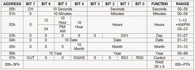
برای نوشتن داده در ds1307RTC باید مراحل زیر را دنبال کنید:
1 – شروع پروتکل I2C،
2 – ارسال آدرس DS1307 که به صورت باینری 11010000 (0x68) است،
3 – ارسال آدرس رجیستر مطابق جدول زیر (به عنوان مثال ثبت ساعت 0x02 است)،
4- مقدار ثبات را بنویسید
5- پروتکل I2C را متوقف کنید.
نوشتن اطلاعات در کد آردوینو ds1307:
بیشتر بخوانید: ساعت Real Time Arduino با استفاده از DS1307
در ادامه، متن انگلیسی این مطلب را میتوانید مشاهده نمایید:
This topic shows how to interface Arduino with DS1307 real time clock to make a clock and calender.
To understand the project and code easily you have to read the datasheet of the DS1307.
DS1307 Pin assignment:
The picture is taken from ds1307 datasheet and it shows the pin assignment of our chip RTC:
Arduino real time clock using DS1307 circuit:
On the circuit schematic there are two buttons used to set the time and date.
The LCD display shows both time and date at the same time, and the LED connected to the ds1307 toggles on and off (can be programmed on the software).
The I2C bus needs pullup resistors to run that why I used the 10K as a pullup resistors.
Arduino real time clock using DS1307 code:
We have to follow the table shown below write/read date to/from ds1307:
To write data to the ds1307RTC you have to follow these steps:
1 – Start I2C protocol,
2 – Send the DS1307 address which is in binary 11010000 (0x68),
3 – Send register address according to the below table (for example hour register is 0x02),
4 – Write register value,
5 – Stop the I2C protocol.
Writing data to ds1307 Arduino code:
Read More: Arduino Real Time Clock Using DS1307
