

زمان برای قسط دیگری در سری نامنظم پروژه های ساعت من است. (یا باید «زمان برای یک قسط دیگر در سری پروژههای ساعت نامنظم» باشد؟) برخلاف « چک زدن » شدید ساعت یک ، در این مقاله نحوه ساخت این ساعت دیجیتال تک رقمی را شرح میدهیم:
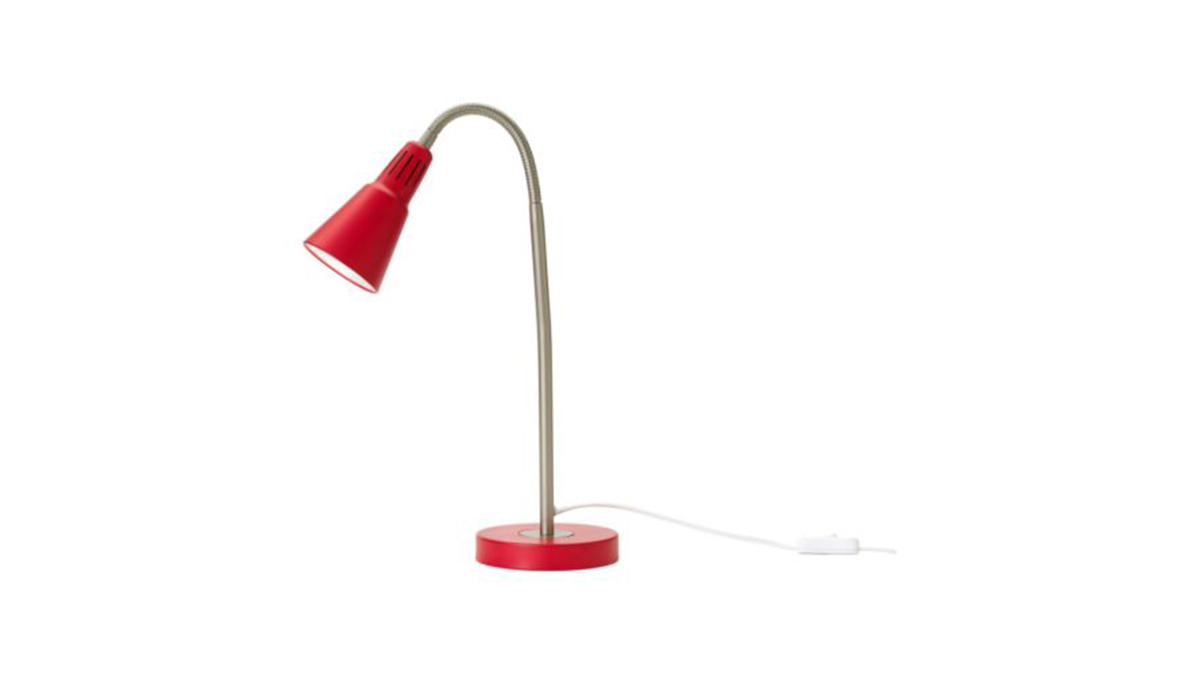
یک بار دیگر لوازم الکترونیکی ساعت از یک برد سازگار با آردوینو ساخته شده و یک آی سی ساعت بلادرنگ DS1307 به برد اضافه شده است. در بالای این، ما یک محافظ با مدار اضافی و دو دکمه اضافه می کنیم - اما بعداً در این مورد بیشتر توضیح خواهیم داد. الهام بخش این ساعت از محصولی است که اخیراً در Ikea خریداری شده است - برای مثال لامپ کار " Kvart ":
هدف این است که لوازم الکترونیکی ساعت را در پایه قرار دهید و یک صفحه نمایش LED تک رقمی در بالای گردن داشته باشید که ارقام را چشمک بزند. دو دکمه در زیر پایه وجود خواهد داشت که برای تنظیم زمان استفاده می شود. انرژی آن توسط یک باتری 9 ولت یا یک آداپتور AC که برای برد معمولی آردوینو مناسب است، تامین می شود.
ساخت و ساز
این مقاله خاطرات ساخت من است و شما همیشه می توانید از دانش و ابتکار خود استفاده کنید. فرض بر این است که شما دانش کاملی از اصول اولیه سیستم آردوینو دارید. اگر نه، سری آموزش های من را که از اینجا در دسترس است مرور کنید. علاوه بر این، با خیال راحت طراحی را برای کار با آنچه در دسترس دارید تغییر دهید - امیدوارم این مقاله بتواند الهام بخش شما باشد.
نرم افزار
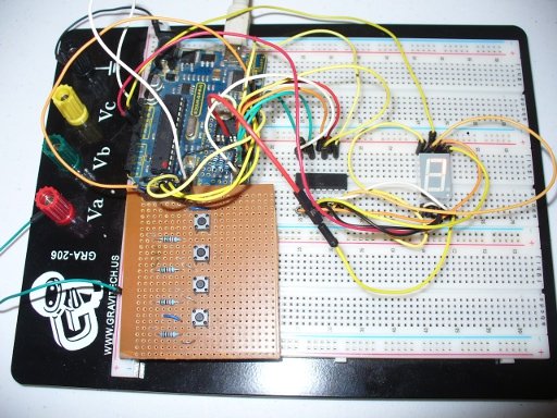
بسیار سادهتر است که ساعت را نمونه اولیه کنید و قبل از خراب کردن لامپ و ساختن ساعت، طرح آردوینو آنطور که دوست دارید کار کند. برای انجام این کار شامل چند سیم بلوز و تخته نان بدون لحیم کاری است، به عنوان مثال:
اگرچه چهار دکمه روی برد وجود دارد، ما فقط از دو دکمه استفاده می کنیم. آنها به پین های دیجیتال هشت و نه (با مقاومت های کششی 10 هزار) متصل می شوند. بخش های نمایشگر LED a~g به ترتیب به پین های دیجیتال آردوینو 0~6 متصل می شوند. نقطه اعشار به پین خروجی پالس DS1307 متصل است - که روی یک خروجی 1 هرتز تنظیم می شود تا یک چشمک زدن ثابت خوب داشته باشد تا نشان دهد ساعت زنده و سالم است.
اگر با کارکردن آی سی ساعت بیدرنگ DS1307 آشنا نیستید، لطفاً این آموزش را مرور کنید . کارکرد ساعت تا حد امکان برای کاربر ساده شده است. برای تنظیم زمان، دکمه A (روی هشت دیجیتال) را فشار می دهند در حالی که زمان فعلی نمایش داده می شود، پس از آن کاربر می تواند اولین رقم (0~2) زمان را با فشار دادن دکمه A انتخاب کند. سپس دکمه B را فشار می دهد. (در دیجیتال نه) آن را قفل کنید و به رقم دوم (0~9) بروید که دوباره با دکمه A انتخاب شده و با دکمه B انتخاب می شود. سپس به همان ترتیب روی ارقام حرکت می کنند.
پس از این فرآیند، زمان جدید از نظر اعتبار بررسی می شود (بنابراین کاربر نمی تواند زمان های نامعتبر مانند 2534h را وارد کند) - و مشکلی ندارد، ساعت دو بار خط فاصله را چشمک می زند و سپس با زمان جدید ادامه می دهد. اگر زمان وارد شده نامعتبر باشد، ساعت به زمان فعلی برمی گردد. این روند در کلیپ ویدیویی زیر نشان داده شده است:
کد پروژه و سایر داده ها:
می توانید طرح آردوینو را از اینجا دانلود کنید .
پروتوشیلد و پین هدر آردوینو نمایشگر LED 7 بخش کاتد مشترک
برای جزئیات بیشتر: ساعت دو - ساعت تک رقمی با استفاده از آردوینو
در ادامه، متن انگلیسی این مطلب را میتوانید مشاهده نمایید:
Time for another instalment in my irregular series of clock projects. (Or should that be “Time for another instalment in the series of irregular clock projects”?) In contrast with the extreme “blinkiness” of Clock One, in this article we describe how to build this single-digit digital clock:
Once again the electronics of the clock will be based from an Arduino-compatible board with a DS1307 real-time clock IC added to the board. On top of this we add a shield with some extra circuitry and two buttons – but more on this later. The inspiration for this clock came from a product that was recently acquired at Ikea – the “Kvart” work lamp, for example:
The goal is to place the electronics of the clock in the base, and have one single-digit LED display at the top of the neck which will blink out the digits. There will be two buttons under the base that are used to set the time. It will be powered by a 9V battery or an AC adaptor which is suitable for a typical Arduino board.
Construction
This article is a diary of my construction, and you can always use your own knowledge and initiative. It is assumed that you have a solid knowledge of the basics of the Arduino system. If not, review my series of tutorials available from here. Furthermore, feel free to modify the design to work with what you have available – I hope this article can be of some inspiration to you.
Software
It is much easier to prototype the clock and get the Arduino sketch working how you like it before breaking down the lamp and building up the clock. To do this involves some jumper wires and a solderless breadboard, for example:
Although there are four buttons on the board we only use two. They are connected to digital pins eight and nine (with 10k pull-down resistors). The LED display segments a~g are connected to Arduino digital pins 0~6 respectively. The decimal point is connected to the pulse output pin of the DS1307 – which will be set to a 1Hz output to have a nice constant blinking to show the clock is alive and well.
If you are unfamiliar with operating the DS1307 real-time clock IC please review this tutorial. Operation of the clock has been made as simple for the user as possible. To set the time, they press button A (on digital eight) while the current time is being displayed, after which point the user can select the first digit (0~2) of the time by pressing button A. Then they press button B (on digital nine) to lock it in and move to the second digit (0~9) which is again chosen with button A and selected with button B. Then they move onto the digits in the same manner.
After this process the new time is checked for validity (so the user cannot enter invalid times such as 2534h) – and is ok, the clock will blink the hyphen twice and then carry on with the new time. If the entered time is invalid, the clock reverts back to the current time. This process is demonstrated in the following video clip:
Project Code and other data:
You can download the Arduino sketch from here.
Arduino protoshield and header pins
common-cathode 7-segment LED display
For more detail: Clock Two – Single digit clock using Arduino
[/membership]