

نمایشگرهای LED هفت بخش روشن تر، جذاب تر هستند و در مقایسه با نمایشگرهای LCD، فاصله دید دور و همچنین زاویه دید وسیع تری را ارائه می دهند. این پروژه یک محافظ نمایشگر LED سریال هفت بخش برای آردوینو Uno یا بردهای سازگار را توصیف می کند. سپر شامل هشت نمایشگر هفت بخش 0.56 اینچی است که توسط یک تراشه MAX7219 هدایت می شوند. این محافظ همچنین دارای یک مقاومت وابسته به نور (LDR) برای اجرای کنترل روشنایی تطبیقی برای نمایشگرهای LED است. خروجی LDR را می توان به کانال ورودی آنالوگ A0 یا A1 آردوینو برای خواندن سطح روشنایی اطراف تغذیه کرد. سپس آردوینو می تواند از این اطلاعات برای تنظیم روشنایی نمایشگرهای LED استفاده کند. یک کد آزمایشی و فایل های Eagle CAD نیز در قسمت آخر مقاله ارائه شده است.
تراشه درایور نمایشگر MAX7219 MAXIM یک رابط سریال 3 سیم (SPI) را برای راه اندازی تا هشت نمایشگر LED هفت بخش (نوع کاتدی معمولی) فراهم می کند. روی تراشه یک رمزگشا BCD، مدار اسکن مالتی پلکس، درایورهای سگمنت و رقم و یک رم ثابت 8×8 برای ذخیره مقادیر ارقام موجود است. حداکثر جریان قطعه برای همه LED ها از طریق یک مقاومت خارجی تنظیم می شود. با این حال، این دستگاه همچنین قادر به ارائه کنترل روشنایی 16 سطحی بخش های LED از طریق نرم افزار است. برای جزئیات بیشتر در مورد بلوک دیاگرام داخلی و عملکرد MAX7219، پروژه قبلی من نمایشگر LED 4 رقمی سریال و همچنین برگه اطلاعات Maxim را بخوانید .
ویژگی های Display Shield
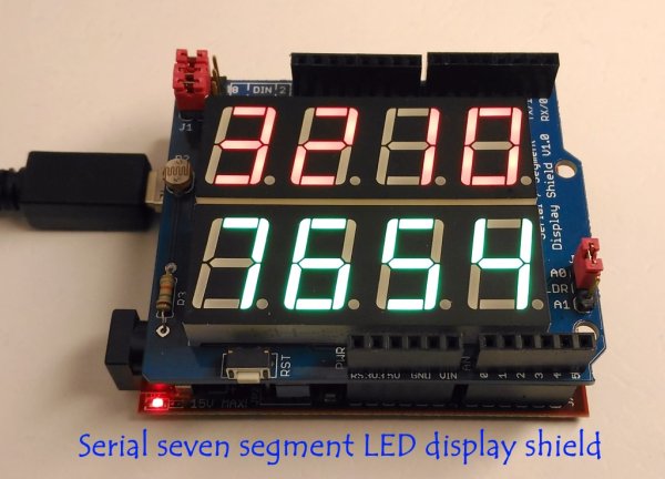
- شامل هشت نمایشگر LED هفت بخش (ارتفاع 0.56 اینچ) است که در دو ردیف چهار رقمی مرتب شده اند.
- پایه های هدر (1) با جامپرهای شنت برای اتصال پایه های DIN، CLK و LOAD MAX7219 به پایه های آردوینو. با جامپرها می توانید DIN را به پایه 8 یا 2، CLK را به پایه 9 یا 3 و LOAD را به پایه 10 یا 4 متصل کنید.
- مدار LDR برای تشخیص سطح نور محیط. خروجی LDR را می توان از طریق جامپر J2 به پین های A0 یا A1 متصل کرد.
این ویژگی ها در تصاویر زیر مشخص شده است.
کنترل روشنایی تطبیقی
تنظیم خودکار روشنایی اساساً یک سیستم حلقه بسته است که توانایی ارزیابی نور محیط و تنظیم روشنایی نمایشگر را دارد. در این شیلد، یک LDR همه منظوره و یک مقاومت با مقدار ثابت (10K) به صورت سری بین منبع تغذیه و پایه های زمین وصل شده اند تا یک شبکه تقسیم ولتاژ ایجاد کنند. مقاومت یک LDR معمولی در شرایط نور روشن کمتر از 1 KΩ است. مقاومت آن می تواند تا چند صد KΩ در شرایط بسیار تاریک افزایش یابد. بنابراین، ولتاژ در مقاومت 10K متناسب با روشنایی اطراف افزایش می یابد. برای تنظیم داده شده، ولتاژ در مقاومت 10K می تواند از 0.1 ولت (در شرایط تاریک) تا بیش از 4.0 ولت (تحت نور بسیار روشن) متفاوت باشد. آردوینو را می توان طوری برنامه ریزی کرد که این ولتاژ آنالوگ را از طریق کانال ورودی آنالوگ خود (A0 یا A1) بخواند و سپس سیگنال های مناسبی را به درایور MAX7219 ارسال کند تا روشنایی نمایشگرهای LED هفت سگمنت را تنظیم کند. من این موضوع را در یکی از مقالات قبلی خود با جزئیات بیشتری توضیح داده ام .
بیشتر بخوانید: سپر نمایشگر LED سریال هفت بخش
در ادامه، متن انگلیسی این مطلب را میتوانید مشاهده نمایید:
Seven segment LED displays are brighter, more attractive, and provide a far viewing distance as well as a wider viewing angle compared to LCD displays. This project describes a serial seven segment LED display shield for Arduino Uno or compatible boards. The shield consists of eight 0.56″ seven segment displays that are driven by one MAX7219 chip. The shield also features a light dependent resistor (LDR) to implement adaptive brightness control to the LED displays. The LDR output can be fed to A0 or A1 analog input channel of Arduino to read the surrounding illumination level. Arduino can then use that information to adjust the brightness of the LED displays. A demo code and Eagle CAD files are also provided in the latter part of the article.
MAXIM’s MAX7219 display driver chip provides a 3-wire serial (SPI) interface to drive up to eight seven-segment LED displays (common-cathode type). Included on the chip are a BCD decoder, multiplex scan circuitry, segment and digit drivers, and an 8×8 static RAM to store the digit values. The maximum segment current for all LEDs is set through an external resistor. However, the device is also capable of providing a 16-level brightness control of the LED segments via software. For more details on the internal block diagram and operation of MAX7219, read my earlier project Serial 4-digit LED display as well as Maxim’s datasheet.
Display Shield Features
- Consists of eight seven segment LED displays (0.56″height) arranged in two rows of four digits.
- Header pins (1) with shunt jumpers for connecting the DIN, CLK, and LOAD pins of MAX7219 to Arduino pins. With jumpers, you can connect DIN to pin 8 or 2, CLK to pin 9 or 3, and LOAD to pin 10 or 4.
- An LDR circuit for detecting ambient light level. The LDR output can be connected to A0 or A1 pins via jumper J2.
These features are highlighted in the pictures below.
Adaptive brightness control
An automatic brightness adjustment is basically a closed loop system that has the capability to assess ambient light and adjust the brightness of the display accordingly. In this shield, a general purpose LDR and a fixed value resistor (10K) are connected in series between the power supply and ground pins to create a voltage dividing network. The resistance of a typical LDR is less than 1 KΩ under bright lighting condition. Its resistance could go up to several hundred KΩ under extremely dark condition. Therefore, the voltage across the 10K resistor increases proportionally with the surrounding illumination. For the given setup, the voltage across the 10K resistor can vary from 0.1V (under dark condition) to over 4.0V (under very bright illumination). Arduino can be programmed to read this analog voltage through its analog input channel (A0 or A1) and then sends out appropriate signals to the MAX7219 driver to adjust the brightness of the seven segment LED displays. I have explained this topic in more detail in one of my previous articles.
Read More: Serial seven segment LED display shield
