

بررسی اجمالی
مدار ساده AC Dimmer برای لامپ های رشته ای. 128 سطح روشنایی قطعات نسبتا ارزان هستند!
چگونه کار می کند
- این یک مدار برش AC است.
- سطح کم نور در جایی تنظیم می شود که شکل موج AC در آن قطع شود. چرخه بیشتر لامپ را روشنتر میکند، کمتر تیرهتر میشود.
- (از digikey http://www.digikey.com/ca/en/techzone/lighting/resources/articles/Retrofit-LED-Bulbs-and-Drivers.html )
عکس
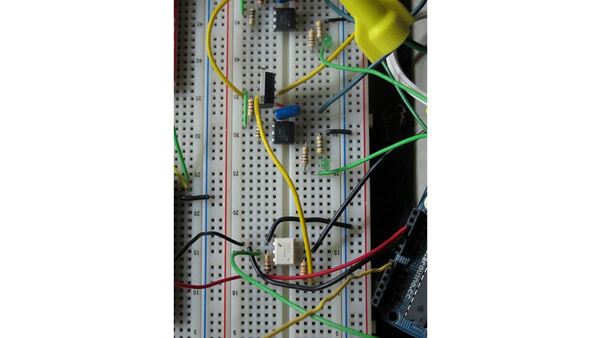 |
- سیگنال های دیجیتال چهار سیگنال سمت چپ. آنها بر روی تابلو برچسب زده شده اند.
- زرد: سیگنال کاهش نور، از پین دیجیتال آردوینو 11 می آید.
- سفید: سیگنال متقاطع صفر، به پین دیجیتال آردوینو 2 اینچی می رود.
- قرمز: منبع تغذیه آردوینو + 5 ولت.
- مشکی: آردوینو GND.
- LED روی برد باید همراه با منبع نور AC کمرنگ یا محو شود. تا زمانی که برق متناوب وصل نشود، محو شدن کار نخواهد کرد، این به اطلاعات صلیب صفر از تراشه H11AA1 بستگی دارد.
- سیگنال های AC چهار طناب سفید در سمت راست. دو کابل پایین سمت راست دوشاخه AC هستند. دو مورد برتر لامپ هستند. اینها روی تخته برچسب گذاری شده اند، اما تا حدی توسط پایانه های پیچ بزرگ پوشانده شده اند.
- پایین برق متناوب - خنثی است.
- پایین وسط برق متناوب - داغ است.
- بالا وسط حباب است – داغ.
- بالا لامپ است - خنثی.
- توجه: برای کمک به تشخیص داغ و خنثی در سیم لامپ، اینجا را ببینید .
کد
- مثال با محو شدن آهسته روشن/خاموش:

- مثال با کنترل پتانسیومتر:

شماتیک
 |
چیدمان تابلو
فایل های PCB
- EagleCAD –

- گربر –

ساخت مدار
قطعات

- 33 هزار
- 10 هزار
- 1K
- 470
- 180
- 2.4K
- خازن 0.01uF
- LED عمومی
- H11AA1 – ورودی 1 کانال AC Optocoupler http://www.jameco.com/webapp/wcs/stores/servlet/Product_10001_10001_18825_-1
- MOC3020 – DIP-6 OPTOISOLATOR Triac Driver http://www.jameco.com/webapp/wcs/stores/servlet/Product_10001_10001_277780_-1
- BTA12-600 – 600 V, 12 A, SNUBBERLESS TRIAC http://www.jameco.com/webapp/wcs/stores/servlet/Product_10001_10001_2034010_-1
از PCB
اگر تعدادی از اینها را ساخته اید، می خواهید PCB بسازید. آموزش ما در مورد پر کردن PCB ساخته شده را ببینید .
برای جزئیات بیشتر: مدار دیمر AC
در ادامه، متن انگلیسی این مطلب را میتوانید مشاهده نمایید:
Overview
Simple AC Dimmer circuit for incandescent bulbs. 128 levels of brightness. Parts are relatively cheap!
How it Works
- This is an AC Chopping Circuit.
- The dim level sets where the AC waveform gets chopped on. More of the cycle makes the bulb brighter, less is dimmer.
- (from digikey http://www.digikey.com/ca/en/techzone/lighting/resources/articles/Retrofit-LED-Bulbs-and-Drivers.html)
Photo
|
- Digital Signals. The four signals on the left. They are labelled on the board.
- Yellow: light dimming signal, comes from Arduino digital pin 11.
- White: zero-cross signal, goes to Arduino digital pin 2 in.
- Red: arduino +5V supply.
- Black: arduino GND.
- The LED on board should dim or fade along with the AC light source. Fading will not work until AC power is connected, it depends on the zero-cross info from the H11AA1 chip.
- AC Signals. The four white cords on the right. The bottom two cables on the right are the AC plug. The top two are the Bulb. These are labelled on the board, but are partially covered by the large screw terminals.
- Bottom is AC Power – Neutral.
- Bottom Middle is AC Power – Hot.
- Top Middle is Bulb – Hot.
- Top is Bulb – Neutral.
- NOTE: For help identifying Hot and Neutral on lamp cord, look here.
Code
- example with slow on/off fade:
- example with potentiometer control:
Schematic
| |
Board Layout
PCB Files
- EagleCAD –
- Gerber –
Building the Circuit
Parts
- 33K
- 10K
- 1K
- 470
- 180
- 2.4K
- 0.01uF capacitor
- generic LED
- H11AA1 – Optocoupler AC Input 1 Channel http://www.jameco.com/webapp/wcs/stores/servlet/Product_10001_10001_18825_-1
- MOC3020 – DIP-6 OPTOISOLATOR Triac Driver http://www.jameco.com/webapp/wcs/stores/servlet/Product_10001_10001_277780_-1
- BTA12-600 – 600 V, 12 A, SNUBBERLESS TRIAC http://www.jameco.com/webapp/wcs/stores/servlet/Product_10001_10001_2034010_-1
From a PCB
If you had some of these manufactured, then you’ll want to build the PCB. See our tutorial on Populating a Fabricated PCB.
For more detail: AC Dimmer Circuit
