

این مقاله و نمودار مدار نشان می دهد که چگونه یک زنگ را به آردوینو وصل کنید وقتی که زنگ با ولتاژ متفاوتی با آردوینو کار می کند. زنگ ممکن است در ولتاژهای 9 ولت، 12 ولت یا برخی ولتاژهای دیگر کار کند. آردوینوهایی مانند Arduino Uno از 5 ولت کار می کنند. تمام ولتاژهایی که در اینجا به آنها اشاره می شود ولتاژهای DC (جریان مستقیم) هستند.
از همان مداری که در اینجا استفاده میشود، میتوان برای کار با زنگ 5 ولتی نیز استفاده کرد، زمانی که زنگ جریان بیشتری نسبت به پین آردوینو میگیرد، بنابراین نمیتوان آن را مستقیماً به پایه آردوینو متصل کرد. برای اتصال مستقیم یک زنگ 5 ولت کم مصرف به آردوینو، به مقاله: اتصال زنگ هشدار به آردوینو Uno مراجعه کنید .
نمودار مدار زنگ آردوینو
مدار نشان داده شده در اینجا از یک ترانزیستور NPN برای اتصال زنگ به آردوینو استفاده می کند. ترانزیستور به آژیر اجازه می دهد تا از ولتاژ متفاوتی به آردوینو تغذیه شود. می توان از هر ترانزیستور NPN که بتواند جریان گرفته شده توسط زنگ را کنترل کند، استفاده کرد.
با مقاومت پایه PN2222 و 2k2، می توان از مدار برای کار با زنگی استفاده کرد که تا حدود 200 میلی آمپر می کشد.
اگرچه مدار نشان میدهد که صدای زنگ از 12 ولت تغذیه میشود، اما مدار اجازه میدهد تا هر زنگ هشداری که از حدود 5 ولت تا حدود 24 ولت کار میکند استفاده شود.
هنگامی که منبع تغذیه خارجی (12 ولت در نمودار مدار) وصل است، GND یا 0 ولت منبع تغذیه باید به GND آردوینو وصل شود.
بنابراین مدار فوق به این معنی است که اتصالات باید به صورت زیر انجام شود:
منبع تغذیه تغذیه کننده زنگ در این مدار یک باتری 12 ولتی است.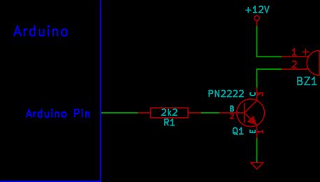
طرح آردوینو
اسکچ آردوینو زیر مدار فوق را با فشار دادن بیژر برای مدت کوتاهی به طور مداوم اجرا می کند.
این ویدیو نشان میدهد که صدای زنگ از باتری 9 ولت و آردوینو از کابل USB تغذیه میشود. آردوینو طرح فوق را اجرا می کند.
برای جزئیات بیشتر: نحوه اتصال زنگ هشدار به آردوینو
در ادامه، متن انگلیسی این مطلب را میتوانید مشاهده نمایید:
This article and circuit diagram show how to connect a buzzer to an Arduino when the buzzer operates at a different voltage to the Arduino. The buzzer may operate at 9V, 12V or some other voltage. Arduinos such as the Arduino Uno operate from 5V. All the voltages referred to here are D.C. voltages (direct current).
The same circuit used here can also be used to operate a 5V buzzer when the buzzer draws more current than the Arduino pin can handle, so can not be connected directly to the Arduino pin. To directly connect a low power 5V buzzer to an Arduino, refer to the article: Connecting a Buzzer to an Arduino Uno.
Arduino Buzzer Circuit Diagram
The circuit shown here uses a NPN transistor to connect the buzzer to the Arduino. The transistor allows the buzzer to be powered from a different voltage to the Arduino. Any NPN transistor that can handle the current drawn by the buzzer can be used.
With a PN2222 and 2k2 base resistor, the circuit can be used to operate a buzzer that draws up to about 200mA.
Although the circuit shows the buzzer being powered from 12V, the circuit allows any buzzer that operates from about 5V to around 24V to be used.
When the external power supply (12V in the circuit diagram) is connected, the GND or 0V of the power supply must be connected to the GND of the Arduino.
So the above circuit means that the connections must be made as follows:
The power supply powering the buzzer in this circuit is a 12V battery.
Arduino Sketch
The Arduino sketch below operates the above circuit by pulsing the buzzer on for a short period of time continuously.
This video shows the buzzer powered from a 9V battery and the Arduino powered from a USB cable. The Arduino is running the above sketch.
For more detail: How To Connect A Buzzer To An Arduino
