

در این پروژه به نحوه ساخت مدار آشکارساز حرارت با استفاده از آردوینو می پردازیم.
مدار آشکارساز حرارتی مداری است که می تواند وجود یا عدم وجود گرما را تشخیص دهد.

این می تواند برای طیف گسترده ای از مدارها از جمله هر دستگاهی که نیاز به نظارت و محافظت در برابر گرمای اضافی دارد مفید باشد. هنگامی که گرمای اضافی به مدار داده می شود، ممکن است برای مدار خطرناک باشد. بنابراین، اگر گرمای بیش از حد تشخیص داده شود، میتوانیم آن را طوری ایجاد کنیم که یک زنگ هشدار، چه نور یا صدا، به ما بگوید که مدار در معرض گرمای خطرناکی قرار گرفته است.
در مدار ما برای این پروژه، زمانی که به آستانه خاصی گرما برسد، یک LED روشن میشود و ما را از این وضعیت آگاه میکند.
دستگاهی که در این پروژه می سازیم ماهیت اتوماتیک خواهد داشت. به محض اینکه گرما به یک آستانه خاص برسد، LED متصل به برد آردوینو ما بلافاصله و به طور خودکار روشن می شود.
برای این پروژه، جزء اصلی که ما استفاده خواهیم کرد ترمیستور است. مقاومت ترمیستور بر اساس میزان حرارتی که در معرض آن قرار می گیرد متفاوت است. در دمای اتاق، یک ترمیستور NTC (ضریب دمای منفی) مقاومتی نزدیک به مقدار مقاومت نامی خود خواهد داشت. بنابراین، برای مثال، یک ترمیستور 100KΩ نزدیک به 100KΩ مقاومت خواهد داشت. با این حال، اگر ترمیستور در معرض گرما قرار گیرد، مقاومت آن به طور قابل توجهی کاهش می یابد و به زیر 40KΩ می رسد. ما میتوانیم از ویژگیهای مقاومت متفاوت آن برای تعیین اینکه آیا مدار ما در معرض سطح بالایی از گرما قرار دارد یا نه، استفاده کنیم. اگر مقاومت ترمیستور بسیار بالا باشد، در معرض حرارت کم قرار می گیرد. اگر خیلی کم باشد در معرض حرارت بالایی قرار می گیرد.
هنگامی که یک ترمیستور را به صورت سری با یک مقاومت قرار می دهیم، یک تقسیم کننده ولتاژ تشکیل می شود. ولتاژ به 2 جزء بر اساس مقاومت مربوط به هر یک تخصیص می یابد. طبق قانون اهم، V=IR، با مقاومت بیشتر، ولتاژ بیشتری در قطعه می افتد. این اصل در این مدار است که ما از آن برای تعیین سطح حرارتی که مدار ما در معرض آن قرار دارد استفاده می کنیم و روشن یا خاموش شدن LED ما را مشخص می کند.
اجزای مورد نیاز برای مدار آشکارساز حرارت
- ترمیستور 100KΩ NTC
- مقاومت 20KΩ
- آردوینو
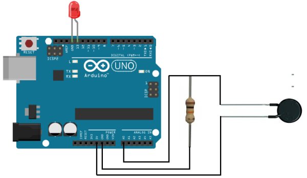
شماتیک مدار آشکارساز حرارت
شماتیک مدار آشکارساز حرارت در زیر نشان داده شده است:
کد
کد روشن کردن LED زمانی که سطح آشکارساز حرارت از یک آستانه خاص بالاتر می رود در زیر نشان داده شده است.
const int ledPin=13; //کد LED متصل به پین 13 را چشمک می زند
. int sensorPin= 0; //پین سنسور به پایه آنالوگ A0 متصل می شود
برای جزئیات بیشتر: نحوه ساخت مدار آشکارساز حرارت با استفاده از آردوینو
در ادامه، متن انگلیسی این مطلب را میتوانید مشاهده نمایید:
In this project, we will go over how to build a heat detector circuit using an Arduino.
A heat detector circuit is a circuit, of course, which can detect the presence or absence of heat.
This could be useful for a wide range of circuits including any device that needs monitoring and protection from excess heat. When excess heat is given to a circuit, maybe this could be dangerous for the circuit. Thus, if too much heat is detected, we can make it so that an alarm, either light or sound, is triggered, telling us that the circuit is being exposed to a dangerous amout of heat.
In our circuit for this project, when a certain threshold is heat is reached, an LED will turn on, alerting us to this situation.
The device we will build in this project will be automatic in nature. As soon as the heat reaches a certain threshold, the LED attached to our arduino board will turn on right away, automatically.
For this project, the main component we will use is a thermistor. A thermistor’s resistance varies based on the amount of heat that it is exposed to. In room temperature, an NTC (negative temperature coefficient) thermistor will have a resistance near its rated resistance value. So, for example, a 100KΩ thermistor will have near 100KΩ of resistance. However, if the thermistor is exposed to heat, its resistance will drop significantly, to below 40KΩ. We can exploit its varying resistance properties to determine if our circuit is being exposed to a high level of heat or if it isn’t. If the thermistor’s resistance is very high, it is exposed to a low level of heat. If it is very low, it is exposed to a high level of heat.
When we place a thermistor in series with a resistor, a voltage divider is formed. Voltage will be allocated to the 2 components based on the each one’s respective resistance. More voltage will fall across the component with the greater resistance, according to ohm’s law, V=IR. This is the principle in this circuit we exploit to determine the heat level that our circuit is exposed to and this will determine whether our LED turns on or off.
Components Needed for the Heat Detector Circuit
- 100KΩ NTC Thermistor
- 20KΩ Resistor
- Arduino
Heat Detector Circuit Schematic
The schematic for the heat detector cirucit is shown below:
Code
The code to turn on an LED when the heat detector level rises above a certain threshold is shown below.
const int ledPin=13; //the code will flash the LED connected to pin 13
const int sensorPin= 0; //Sensor pin connects to analog pin A0
For more detail: How to Build a Heat Detector Circuit Using an Arduino
