

در این پروژه به بررسی نحوه ساخت مدار سروو موتور با استفاده از آردوینو می پردازیم.
این مداری است که می تواند سروو موتور را کنترل کرده و بچرخاند تا مقدار مشخصی درجات بچرخد.
به طور خاص، در مدار خود، آن را طوری می کنیم که سروو موتور 180 درجه بچرخد و سپس متوقف شود و سپس 180 درجه به عقب بچرخد (در جهتی که شروع شده است).
برای کنترل سروو، آن را به برد آردوینو متصل می کنیم و سپس آن را طوری برنامه ریزی می کنیم که به روشی که قبلاً گفته شد بچرخد. خواهیم دید که چگونه این کار را در کد انجام می دهیم.

پس زمینه سرووها
سرووها موتورهایی هستند که برای کنترل دقیق حرکت فیزیکی استفاده می شوند. این به این دلیل است که آنها معمولا به جای چرخش مداوم به یک موقعیت حرکت می کنند. آنها برای چرخش چیزی در محدوده 0 تا 180 درجه ایده آل هستند.
سرووها به راحتی به آردوینو متصل می شوند و کنترل می شوند، زیرا درایور موتور در سروو تعبیه شده است. این بدان معنی است که مدار درایور برای کارکرد موتور به صورت داخلی در سروو ساخته شده است. بنابراین ما مجبور نیستیم یک مدار درایور را وصل کنیم، زیرا از قبل وصل شده است. بنابراین، تمام کاری که ما انجام میدهیم این است که پایههای سروو را مستقیماً به برد آردوینو وصل کرده و آن را برنامهریزی کنیم، و این تنها کاری است که باید انجام شود.
در داخل، سروو موتورها شامل یک موتور کوچک هستند که از طریق چرخ دنده ها به یک شفت خروجی متصل می شود. شفت خروجی یک بازوی سروو را به حرکت در می آورد و همچنین به یک پتانسیومتر متصل می شود تا بازخورد موقعیت را به مدار کنترل داخلی ارائه دهد.
سرووهای چرخش پیوسته که بازخورد موقعیتی آنها قطع شده است، می توانند به طور مداوم در جهت عقربه های ساعت و خلاف جهت عقربه های ساعت با مقداری کنترل بر سرعت بچرخند. اینها مانند موتورهای برس دار عمل می کنند، با این تفاوت که سرووهای چرخش پیوسته به جای analogWrite از کد کتابخانه سروو استفاده می کنند و نیازی به محافظ موتور ندارند. معایب آن این است که انتخاب های سرعت و قدرت در مقایسه با موتورهای خارجی محدود است و دقت کنترل سرعت معمولاً به خوبی محافظ موتور نیست (زیرا الکترونیک برای موقعیت یابی دقیق طراحی شده است نه کنترل سرعت خطی).
اجزای مورد نیاز
- سروو موتور
- آردوینو
- هدر نر به نر 3 پین
سروو موتور شرکت Parallax یک موتور استاندارد خوب است که می تواند برای این پروژه استفاده شود. این موتوری است که می تواند هر موقعیتی را بین 0 تا 180 درجه نگه دارد. و بین ولتاژ کاری 4 ولت تا 6 ولت دی سی کار می کند. بنابراین، می تواند با پایه پاور متصل به ترمینال 5 ولت آردوینو به خوبی کار کند.
موتور را می توانید در سایت Parallax در لینک زیر پیدا کنید: Parallax- Standard Servo Motor .
برگه اطلاعات موتور را می توانید در لینک زیر مشاهده کنید: صفحه اطلاعات سرو موتور Parallax .
موتور دارای 3 ترمینال، پایه پاور، زمین و خروجی است.
ترمینال های مختلف پین در سروو موتور با رنگ آنها متمایز می شوند. سیم قرمز پین ولتاژ مثبت است. این پایه ای است که 5 ولت را از پین آردوینو تغذیه می کند تا بتوان برق را تغذیه و اجرا کرد. سیم مشکی زمین است. این به ترمینال زمین برد آردوینو متصل می شود. سیم سفید سیم ورودی/خروجی است. به پین خروجی دیجیتال D9 آردوینو متصل می شود.
| سیم اختلاف منظر | به ترمینال آردوینو متصل می شود |
| سیم قرمز | ترمینال +5 ولت |
| سیم سیاه | ترمینال GND |
| سیم سفید | D9 (پین خروجی دیجیتال) |
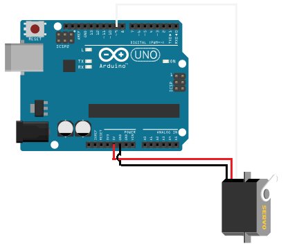
شماتیک مدار سروو موتور
شکل مداری که خواهیم ساخت در زیر نشان داده شده است.
برای جزئیات بیشتر: نحوه ساخت مدار سروو موتور (با آردوینو)
در ادامه، متن انگلیسی این مطلب را میتوانید مشاهده نمایید:
In this project, we will go over how to build a servo motor circuit using an arduino.
This is a circuit which can control and rotate a servo motor to rotate a certain amount of degrees.
Specifically, in our circuit, we will make it so that the servo motor rotates 180 degrees and then stops and then rotates 180 degrees back (in the direction it began).
To control the servo, we connect it to the arduino board and then program it so that rotates in the manner discussed before. We’ll see how we do this in code.
Background on Servos
Servos are motors that are used to accurately control physical movement. This is because they generally move to a position instead of continuously rotating. They are ideal for making something rotate over a range of 0 to 180 degrees.
Servos are easy to connect to the arduino and control, because the motor driver is built into the servo. This means that the driver circuit to operate the motor is internally constructed into the servo. So we don’t have to connect a driver circuit, since it already is connected. Thus, all we do is connect the pins of the servo directly to the arduino board and program it, and that’s all that needs to be done.
Internally, servo motors contain a small motor connected through gears to an output shaft. The output shaft drives a servo arm and is also connected to a potentiometer to provide position feedback to an internal control circuit.
Continuous rotation servos that have positional feedback disconnected can rotate continuously clockwise and counterclockwise with some control over the speed. These function like brushed motors, except that continuous rotation servos use the servo library code instead of analogWrite and don’t require a motor shield. The disadvantages are that the speed and power choices are limited compared to external motors, and the precision of speed control is usually not as good as with a motor shield (since the electronics is designed for accurate positioning, not linear speed control).
Components Needed
- Servo Motor
- Arduino
- 3 pin male to male header
The servo motor from Parallax is a good standard motor that can be used for this project. It is a motor that can hold any position between 0 and 180 degrees. And it works between a operating voltage of 4V to 6VDc. Thus, it can function well with the power pin connected to the 5V terminal of the arduino.
The motor can be found at the Parallax site at the following link: Parallax- Standard Servo Motor.
The datasheet for the motor can be found at the following link: Parallax Servo Motor Datasheet.
The motor has 3 terminals, the power pin, ground, and output.
The different pin terminals are differentiated on the servo motor by their colors. The red wire is the positive voltage pin. This is the pin that gets fed the 5V from the arduino pin so that the power can be powered and run. The black wire is ground. This gets connected to the ground terminal of the arduino board. The white wire is the I/O wire. It gets connected to digital output pin D9 of the arduino.
| Parallax Wire | Connects to Arduino Terminal |
| Red Wire | +5V terminal |
| Black Wire | GND terminal |
| White Wire | D9 (digital output pin) |
Servo Motor Circuit Schematic
The circuit shcematic we will build is shown below.
For more detail: How to Build a Servo Motor Circuit (with Arduino)
