

این یک مدار شمارنده ساده 0 تا 9 است که با استفاده از آردوینو ساخته شده است! در اینجا یک نمایشگر LED 7 قطعه ای کاتد معمولی برای نمایش ارقام به آردوینو متصل می شود.
کد (اسکچ آردوینو) اجازه می دهد تا دکمه فشاری شمارنده را از 0 به 9 افزایش دهید.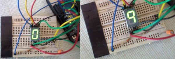
کل مدار را می توان از یک باتری استاندارد 9 ولت PP3/6F22 یا از هر آداپتور برق مناسب آردوینو تغذیه کرد. نمایشگر هفت بخش در واقع یک دستگاه بسیار ساده است. این ترکیبی از 8 LED است (نقطه اعشار -DP- 8 است) که می توان آنها را طوری مرتب کرد که از ترکیب های مختلف برای ساخت ارقام عددی استفاده شود.
جزئیات یک صفحه نمایش LED 7 سگمنت معمولی کاتد در اینجا نشان داده شده است. توجه داشته باشید که پایه های 3 و 8 نمایشگر پایانه های کاتد هستند.
برای ساخت کل پروژه، فقط نمودار مدار شماتیک را دنبال کنید.
پین های 2، 3، 4، 5، 6، 7 و 8 آردوینو باید به ترتیب صحیح به نمایش پین های 7، 6، 4، 2، 1، 9 و 10 بروند. در صورت شک به این جدول مراجعه کنید. نقطه ورودی Push Switch (S1) در پایه 9 آردوینو است.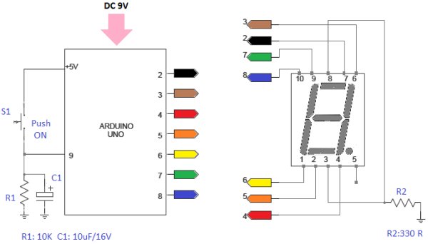
اتصال مستقیم پین های نمایشگر به پین های ورودی/خروجی آردوینو عمل خوبی نیست. برای هدف آزمایش فقط یک مقاومت 330 اهم (R2) بین ریل زمین (0V) و پایه های کاتد مشترک (3 و 8) اضافه می شود. بهتر است پایه های 3 و 8 نمایشگر را مستقیماً به ریل زمینی متصل کنید. سپس یک مقاومت 330 اهم بین هر یک از اتصالات دیگر به آردوینو اضافه کنید.
برای جزئیات بیشتر: نمایشگر و شمارنده LED قطعه ۷ آردوینو – آموزش شماره ۸
در ادامه، متن انگلیسی این مطلب را میتوانید مشاهده نمایید:
This is a simple 0 to 9 counter circuit constructed using Arduino! Here, a common cathode 7-segment LED display is connected to Arduino for displaying the digits.
The code (Arduino sketch) allows push button increment of the counter from 0 to 9.
The whole circuit can be powered from a standard 9V PP3/6F22 battery, or from any suitable Arduino power adaptor.The seven segment display is infact a very simple device. It is a combination of 8 LEDs (the decimal point -DP- is the 8th), which can be arranged so that different combinations can be used to make numerical digits.
Details of a common cathode type 7 segment LED display is shown here. Note that pins 3 and 8 of the display is the cathode terminals.
Just follow the schematic circuit diagram to make the entire project.
Arduino pins 2, 3, 4, 5, 6, 7 and 8 should go to Display pins 7, 6, 4, 2, 1, 9 and 10 in correct order. In case of any doubt refer this table. Push Switch (S1) input point is at pin 9 of the Arduino.
Connecting the display pins directly to Arduino I/O pins is not a good practice. For testing purpose only one 330 Ohm resistor (R2) is added between ground rail (0V) and the common cathode pins (3 & 8). It is better to directly connect pins 3 & 8 of the display to ground rail. Next add a 330 Ohm resistor between each of the other connections to the Arduino.
For more detail: Arduino 7 Segment LED Display and Counter – Tutorial #8
