

شیلد آردوینو با هدف کلی برای ماشین های خود متعادل کننده.

چرا درستش کردم؟
من قبلاً در سال 2010 یک Instructable درباره نحوه ساخت یک اسکیت برد خود متعادل ساختم.
http://www.instructables.com/id/Easy-build-self-balancing-skateboardrobotsegway-/
بیش از 500 نظر در این مورد وجود دارد و بسیاری از آنها در تنظیم حسگرهای تعادل، نرم افزار و لوازم الکترونیکی سردرگمی را بیان می کنند. علاوه بر این، واحدهای اندازه گیری اینرسی خروجی آنالوگ که معمولاً در دسترس بودند، ساخته نشدند.
در اینجا، من یک IMU آنالوگ مبهم با قیمت پایین انتخاب کردم که در حال حاضر هنوز در چین ساخته می شود، و در ebay موجود است، و از یک "سپر" نمونه اولیه آردوینو برای نصب تمام قطعات، از جمله یک کابل به یک کنترل کننده دستی اصلی استفاده کردم. فرمان و تنظیم دقیق نقطه تعادل) و یک کابل فقط با 2 سیم که به کنترل کننده قدرت موتور 2 × 25 آمپر "Sabertooth" وصل می کنید.
من سعی کرده ام ساخت آن را تا حد امکان آسان و به طور خاص، غیر گیج کننده کنم.
توجه دسامبر 2013: حتی اینها هم اکنون نادر هستند، اما من به تازگی سری حسگرهای آنالوگ "Grove" را از Seedstudio پیدا کردم و جزئیات تماس را به صفحه 6 اضافه کردم.
در اصل یک بازسازی کامل سیستم کنترل است که ساخت آن را در همان زمان ساده تر می کند.
این با اسکیتبردهای خود متعادل کننده من کار میکند، اما با آزمایش مقادیر P، I و D که در ابتدای برنامه ذکر شدهاند (طرح آردوینو) باید بتوانید از آن برای ساخت یک کلون SegwayTM یا پروژه مشابه استفاده کنید .
من اصول اولیه نحوه اتصال این را به کنترل کننده برق موتور Sabertooth، که یک کنترل کننده برق ربات تجاری خارج از قفسه است، نحوه تغذیه Sabertooth و نحوه اتصال موتورها به آن آورده ام. برای توضیح واقعاً دقیق جنبه مکانیکی ساخت، به Instructable اصلی من در سال 2010 که در بالای این صفحه معرفی لینک شده است، نگاهی بیندازید.
یک ژیروسکوپ برای بالانس (فیلتر مکمل با شتاب سنج) استفاده می شود. ژیروسکوپ دیگری سرعت چرخش را به صورت جانبی اندازه گیری می کند (به عنوان مثال هنگام فرمان).
این ویژگی مفید دیگری را به صورت رایگان فراهم می کند. هنگامی که در یک خط مستقیم کار می کند، اگر چرخش بیشتر از 10 درجه در ثانیه را به صورت جانبی تشخیص دهد، قدرت موتورها را برای مقاومت در برابر این اثر تغییر می دهد. به عنوان مثال، موتورها اغلب اصطکاک متفاوتی دارند، به طوری که وقتی شما سرعت توقف را کاهش می دهید، یکی قبل از دیگری متوقف می شود و شما می چرخید. این ویژگی این اتفاق را متوقف می کند و به این معنی است که چرخ ها را می توان کاملاً نزدیک به هم سوار کرد.
این ویدیو را ببینید http://www.youtube.com/watch?v=FEaTxahyQxc و خواهید دید که این اتفاق در 0.51 دقیقه رخ می دهد، ژیروسکوپ یدکی برای کاهش این اثر استفاده می شود.
لیست قطعات اصلی شماره قطعه www.maplin.com GBP US$ N39KR RockerSwitch 2.39 3.62 کابل چند هسته ای 9 راه XR27E 5.14 7.79
N39KR RockerSwitch 2.39 3.62
GW72P Microswitch with lever 2.49 3.77
FH04E Sub-Min Toggle switch 2.79 4.23
Project Box 3.749 .
کابل 2 هسته ای 0.99 1.50
N30KU آردوینو Uno 24.99 37.86
N35KU آردوینو پروتوشیلد 14.99 22.71
5DOF آنالوگ 5DOF 17.91
به روز رسانی آنالوگ IMU2TE از 17.91th. 2013 (برای لیست به مرحله 6 مراجعه کنید)
4 x LED 2.56 3.88
_________________________________________________________________
80.33 121.71
مرحله 1: کل مونتاژ با کنترل دستی
این Instructable فرض می کند که شما اصول اولیه نحوه بارگذاری یک برنامه یا "اسکچ" را در میکروکنترلر آردوینو می دانید و همچنین می دانید که چگونه لحیم کاری کنید.
نکته:
حتی اگر فکر میکنید که میتوانید به خوبی ببینید، یک جفت ذرهبین یا گیره بزرگنما که در بسیاری از فروشگاههای سرگرمی فروخته میشود، تفاوت زیادی در لحیم کاری قطعات بسیار کوچک ایجاد میکند و احتمالاً تمام عمرتان را دوام میآورد.
Shield دارای پینهای بلندی است که به شما امکان میدهد پس از تکمیل آن را روی آردوینو فشار دهید. مراقب خم کردن برخی از آنها به همان اندازه که انجام می دهید، باشید. دارای یک شبکه مربعی از سوراخ های لحیم کاری است که می توانید اجزای خود را روی آن نصب کنید. من IMU، چراغهای نشانگر LED و کابلها را به کنترلکننده موتور sabertooth و کنترلکننده دستی را نیز به طور ایمن روی آن نصب میکنم.
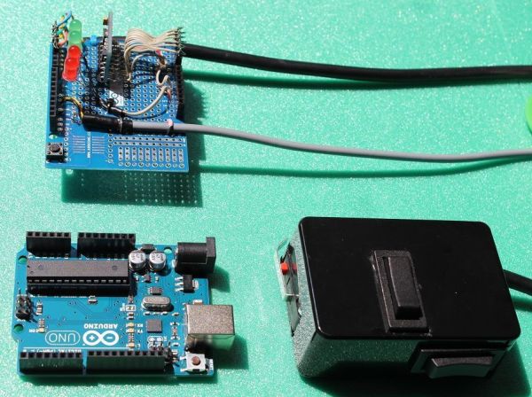
سپر بالا سمت چپ در این عکس است. Arduino UNO پایین سمت چپ است. کنترل کننده دستی که ما نیز می سازیم پایین سمت راست است.
مرحله 2: طرح ساخت کلی ماشین
این فقط یک راهنما است که چگونه میتوانید با استفاده از باتریهای مهر و موم شده با اسید سرب و دو واحد چرخمحرک عقب از یک اسکوتر برقی بچهگانه، مکانیکهای ماشینی مانند این را بسازید.
برای مثال نحوه چیدمان مکانیک ها، دستورالعمل قبلی من در سال 2010 را ببینید.
http://www.instructables.com/id/Easy-build-self-balancing-skateboardrobotsegway-/
مرحله 3: قطعات اصلی چیده شده اند
کابل Arduino Uno
Arduino protoshield (یا چیزی بسیار مشابه)
با حداقل 6 سیم در داخل (در واقع مال من 9 هسته ای بود).
نگهدارنده باتری برای 6 باتری AA 1.5 ولت.
دو کلید راکر که وقتی آنها را رها می کنید روی فنر به حالت وسط برمی گردند
یک میکروسوئیچ با اهرم فلزی که ما از آن به عنوان سوئیچ مرد مرد استفاده خواهیم کرد (وقتی آن را رها کنید تمام نیروی موتور قطع می شود).
کلید روشن/خاموش کوچک که جعبه باتری را به آردوینو متصل می کند.
کانکتور برای جعبه باتری.
جعبه پروژه پلاستیکی که ما کنترل کننده دستی خود را از آن می سازیم.
نزدیک سپر
IMU به صورت عمودی روی آن نصب میشود، بعداً بیشتر روی آن (در این عکس اولیه سیمهای بیشتری از آنچه در نهایت نیاز داشتم).
ما 4 نشانگر LED داریم.
کابل چند هسته ای کنترل دستی در پایین سمت چپ قرار دارد.
کابل 2 هسته ای به کنترل کننده برق موتور Sabertooth از برد وسط سمت راست خارج می شود.
شیلد در بالای آردوینو انباشته شده است.
مرحله 5: پین های هدر با زاویه راست IMU
در عکس قبلی IMU به صورت عمودی روی Shield نصب شده بود. این به این دلیل بود که من از پینهای هدر زاویهدار برای نصب آن استفاده کردم که به راحتی با IMU ارائه میشوند.
انتهای بلند از لبه تخته با سوراخ های لحیم کاری در امتداد آن عبور می کند، انتهای کوتاه از طریق سوراخ های محافظ اولیه پایین می رود.
مرحله 6: چگونه IMU را سیم کشی می کنیم
تعداد زیادی IMU خروجی آنالوگ وجود ندارد.
اینجا تنها موردی است که به نظر می رسد هنوز ساخته شده است.
وضعیت IMU (به روز شده در 25 آگوست 2013). وضعیت دائماً در حال تغییر…………………….
آنچه شما برای کار بدون تغییر این نرم افزار نیاز دارید، یک IMU آنالوگ حاوی ژیروسکوپ IDG655 و شتاب سنج ADXL335 است.
این یکی اصلی است که من هنگام نوشتن دستورالعمل مشخص کردم. با این حال اکنون 6 عدد باقی مانده و قیمت چهار برابر شده و به 96.99 دلار رسیده است (با تشکر از بچه ها)
http://www.ebay.com/itm/181004141876?ssPageName=STRK:MEWNX:IT&_trksid=p3984.m1439.l2649
این یکی تقریباً خوب به نظر می رسد. 17 دلار اما توجه داشته باشید که "حمل و نقل و جابجایی" 100 دلار است (!) باز هم ممنون بچه ها.
http://www.ebay.com/itm/1PC-5DOF-IDG655-ADXL335-Accelerometer-Dual-axis-Gyro-Instrument-Module/360673380095?rt=nc&_trksid=p2047675.m185ms22000000.m18512%300000. FIT%26ao%3D1%26asc%3D17214%26meid%3D818663122151966103%26pid%3D100005%26prg%3D8039%26rk%3D3%26rkt%3D38%215%26%3D301%26%
این یکی خوب است اما به عنوان فروخته شده فهرست شده است
http://www.dhgate.com/product/gy-66-idg655-adxl335-module-5dof-module-twin/156501775.html
مواردی که به نظر می رسد در حال حاضر با قیمت مناسب در دسترس هستند:
GY – 66 5 DOF سنسور ژیروسکوپ آنالوگ دو محوره IDG655 ADXL335 ماژول
17.59 دلار به انگلستان ارسال نمی شود، به جاهای دیگر ارسال می شود.
http://www.ebay.com/itm/GY-66-5-dof-biaxial-analog-gyroscope-sensor-IDG655-ADXL335-module-/181115375225
GY-66 IDG655 ADXL335 ماژول 5DOF سنسور ژیروسکوپ دو پیچ آنالوگ تعداد ارسال رایگان
14.28 دلار
http://www.aliexpress.com/store/product/GY-66-IDG655-ADXL335-Module-5DOF-Alog-Scre -تعداد-ژیروسکوپ-سنسور-ارسال-رایگان/406986_729113614.html
این یکی خوب به نظر می رسد. ارسال به بریتانیا، ایالات متحده و غیره.
22.20 دلار
http://dx.com/p/gy-66-5dof-idg655-adxl335-double-shaft-analog-quantity-gyroscope-sensor-module-blue-232963
اینجا دوباره 24.71 دلار است
http://www.goodluckbuy.com/gy-66-5dof-dual-axis-analog-gyroscope-sensor-module-idg655-adxl335.html
توجه دسامبر 2013: به تازگی سری حسگرهای آنالوگ "Grove" را از Seedstudio پیدا کردهاید. جزئیات زیر. فاکتورهای مقیاسگذاری در نرمافزار ممکن است نیاز به اصلاح داشته باشند، اما حداقل هنوز برای خرید در دسترس هستند:
شتابسنج آنالوگ سه محوره
http://www.seeedstudio.com/wiki/Grove_-_3-Axis_Analog_Accelerometer
از اینجا بخرید:
http://www.seeedstudio. com/depot/grove-3axis-analog-accelerometer-p-1086.html
و اینجا:
http://www.dawnrobotics.co.uk/grove-3-axis-analog-accelerometer-adxl335/?gclid=CNDQ9fzmqLsCFSoewwod7gYA_w
آنها همچنین یک شتابسنج آنالوگ 3 محوری انجام میدهند:
اینجا خرید کنید:
http://www.seeedstudio.com/depot/grove-single-axis-analog-gyro-p-1451.html
و اینجا:
http://www.dawnrobotics. co.uk/grove-single-axis-analog-gyro/
به تازگی اینها را نیز پیدا کردم (17 دسامبر 2013)
به نظر می رسد اینها نیز آنها را در انبار دارند:
http://www.dawnrobotics.co.uk/grove-single-axis-analog-gyro/?gclid=COyekqahuLsCFRMRtAodlVMAQA
این یکی نیز ممکن است کار کند، 10 تا در ebay باقی مانده است.
http://www.ebay.co.uk/itm/Single-axis-gyroscope-analog-gyro-module-ENC-03MB-module-For-Arduino-MWC-/180956189552?_trksid=p2054897.l4275
برای تعادل فقط به یک ژیروسکوپ نیاز دارید. من از دومی برای پایداری جهت استفاده می کنم، اما آن یکی ضروری نیست (یا 2 ژیروسکوپ تک محوری بخرید.
شتاب سنج را می توان جداگانه خریداری کرد:
مثال در اینجا:
http://www.ebay.co.uk/itm/ADXL335-3-axis-Analog-Output-Accelerometer-Module-angular-transducer-/281048570799?pt=LH_DefaultDomain_0&hash=item416fccdbaf
بررسی کنید که نمونه اصلی که استفاده کردم چگونه از طریق پروتوشیلد به آردوینو متصل شده است:
برق اتصال VCC 3.3 ولت از پایه 3.3 ولت آردوینو است، نه پایه 5 ولت که ژیروسکوپ را منفجر می کند، می دانم، قبلاً این کار را انجام داده ام. مراقب باشید، این پین ها و GND روی پین های آردوینو و پروتوشیلد مربوطه به هم نزدیک هستند، اجازه ندهید پل های لحیم کاری بین آنها ایجاد شود! (یک مورد خوب برای ذره بین هایی که قبلا ذکر کردم).
GND به یکی از پایه های GND روی پروتوشیلد می رود.
فقط 3 اتصال دیگر باید ایجاد شود:
X4.5 به آنالوگ پین 3 در پروتوشیلد آردوینو می رود.
Y4.5 به پین آنالوگ 2 می رود
Z-acc به پایه آنالوگ 1 می رود
بقیه حفره های IMU که لازم نیست نگران باشید، نیازی نیست………………خیلی بد نیست؟
نکات مربوط به این IMU:
شتاب سنج (ADXL335) یادداشت ها: 300 میلی ولت (0.3 ولت) در هر گرم یعنی در زاویه 90 درجه
GYRO یادداشت هایی در IMU چینی ما فقط در سال 2013 موجود است که از ماژول ژیروسکوپ IDG655 استفاده می کند: خروجی ژیروسکوپ 4.5 x در این IMU چینی : 2.27 میلی ولت در هر درجه در ثانیه تا 500 درجه در ثانیه.
مرحله 7: برق 3.3 ولت به IMU (نه 5 ولت)
اینطوری انجامش دادم تا زمانی که سیم ها به پین های مناسب بروند، می توانید این کار را هر طور که دوست دارید انجام دهید.
من انتهای بلند پین های هدر با زاویه سمت راست را در IMU قرار دادم و همه آنها را به سوراخ های IMU مربوطه لحیم کردم.
از انتهای پین های بلند (اکنون به صورت افقی بالای Protoshield بیرون زده اند) سیم های کوچکی را با احتیاط به پین های آنالوگ 1، 2 و 3 کشیدم، در عکس بعدی می توانید این را بهتر ببینید.
دو سیم بلندتر به پایه منبع تغذیه 3.3 ولت و همچنین به یکی از پایه های GND می رسد.
سوراخ های پروتوشیلد زیر IMU فقط برای نگه داشتن IMU به صورت عمودی و به عنوان یک پایه برای آن استفاده می شود. من دو تا از آنها را لحیم کردم تا IMU را به طور سفت و سخت در زاویه 90 درجه نسبت به پروتوشیلد، یعنی عمودی نگه دارم.
سوراخهای روی محافظ اولیه که درست در داخل سوکتهای پین سیاه قرار دارند، با آنها تداوم دارند. بنابراین می توانید پین های هدر را در سوکت ها قرار دهید و سیم های خود را به آنها لحیم کنید (همانطور که در اینجا با سیم های IMU من به ورودی های آنالوگ 1،2 و 3 مشاهده می شود) یا می توانید سیم های خود را به سوراخ های کنار هر پایه لحیم کنید (همانطور که با سیم 3.3 ولت و سیم GND در این عکس).
مرحله 8: بقیه سیم کشی IMU، فقط 3 سیم
همانطور که در صفحه قبل توضیح داده شد، من 3 سیم کوتاه را از انتهای هوای پین های هدر بلند IMU (z-acc، X4.5 و Y4.5) به ورودی های آنالوگ 1، 2 و 3 زدم.
2 سیم دیگر از VCC و GND به ترتیب به پایه های 3.3 ولت و GND روی پروتوشیلد می روند.
برای جزئیات بیشتر: پروژه اسکیت برد/segw*y خود متعادل کننده آردوینو شیلد
در ادامه، متن انگلیسی این مطلب را میتوانید مشاهده نمایید:
General purpose Arduino shield for self-balancing machines.
Why did I make it?
I previously made an Instructable in 2010 on how to build a self-balancing skateboard.
http://www.instructables.com/id/Easy-build-self-balancing-skateboardrobotsegway-/
There are >500 comments on this and many express confusion setting up the balance sensors, software and electronics. On top of that, the analog output inertial measurement units that were commonly available stopped being made.
Here, I have taken a low price obscure analog IMU that IS currently still made in China, that IS available on ebay, and used an Arduino prototyping “shield” to mount ALL the parts, including a cable to a basic hand-controller (for steering and fine-tuning the balance point) and a cable with just 2 wires that you connect to a 2 x 25Amp “Sabertooth” motor power controller.
I have tried to make it as easy and in particular, non-confusing as possible to build.
NOTE December 2013: Even these are getting rare now but I have just found the “Grove” series of analog sensors from Seedstudio and added contact details to page 6.
In essence a complete re-vamp of the control system, making it simpler to build at the same time.
It works with my self-balancing skateboards but by experimenting with the P, I, and D values listed at the start of the program (Arduino sketch) you should be able to use it to build a SegwayTM clone or similar project.
I have included the basics of how to connect this to the Sabertooth motor power controller, which is an off the shelf commercial robot power controller, how to power the Sabertooth and how to connect the motors to it. For a really detailed explanation of the mechanical side of the build, take a look at my original Instructable of 2010, linked at the top of this introduction page.
One gyro is used for balancing (complementary filter with an accelerometer). Another gyro measures rate of rotation laterally (e.g. when steering).
This provides another useful feature for free; when running in a straight line, if it detects rotation faster than 10 degrees per second laterally, it will change power to the motors to resist this effect. For example the motors often have different friction so when you slow to a stop, one stops before the other and you spin off. This feature stops that happening, and means the wheels can be mounted quite close together.
See this video http://www.youtube.com/watch?v=FEaTxahyQxc and you will see this happening at 0.51 mins, the spare gyro is used to reduce this effect.
Main parts list
www.maplin.com part number GBP US$
N39KR RockerSwitch 2.39 3.62
N39KR RockerSwitch 2.39 3.62
GW72P Microswitch with lever 2.49 3.77
FH04E Sub-Min Toggle switch 2.79 4.23
Project Box 3.79 5.74
XR27E 9 way multicore cable 5.14 7.79
2 core screened cable 0.99 1.50
N30KU Arduino Uno 24.99 37.86
N35KU Arduino protoshield 14.99 22.71
5DOF analog IMU 17.81 26.99
NOTE: List of sellers of this updated August 25th 2013 (See Step 6 for the list)
4 x LED’s 2.56 3.88
_________________________________________________________
80.33 121.71
Step 1: Whole assembly with hand controller
This Instructable assumes you know basics of how to load a program or “sketch” into an Arduino microcontroller and also know how to solder.
Tip:
Even if you think you can see just fine, a pair of magnifying glasses or magnifying visor as sold in many hobby shops makes a huge difference when soldering very small parts and will last you your whole life probably.
The Shield has long pins that allow you to push it on top of the Arduino when completed. Take care as quite easy to bend some of them as you do it. It has a square grid of solder-holes on which you can mount your own components. I will mount my IMU, my LED indicator lights and the cables to the sabertooth motor controller and the hand controller securely to it also.
The shield is top left in this photograph. Arduino UNO is lower left. Hand controller, which we shall also make is lower right.
Step 2: General build layout of machine
This is just a guide as to how you might lay out the mechanicals of a machine like this using lead-acid sealed batteries and two rear-wheel drive units from a chain driven electric children’s scooter.
See my previous Instructable of 2010 for example of how to arrange the mechanicals.
http://www.instructables.com/id/Easy-build-self-balancing-skateboardrobotsegway-/
Step 3: Main parts laid out
Arduino Uno
Arduino protoshield (or something very similar)
Cable with at least 6 wires inside (mine was 9 core in fact).
Battery holder for 6 x AA 1.5V batteries.
Two rocker switches that return to the middle position on a spring when you let go of them
A microswitch with metal lever that we will use as our deadman switch (when you let go of it all power to motors is cut).
Small on/off switch connecting the battery box to the Arduino.
Connector for the battery box.
Plastic project box which we will make our hand controller from.
Close up of the shield.
The IMU is mounted on it vertically, more on this later (more wires in this early photo than I eventually needed).
We have 4 indicator LED’s.
Multicore cable from hand controller comes in lower left.
2 core cable to Sabertooth motor power controller exits board middle right.
Shield is stacked on top of the Arduino.
Step 5: IMU right angled header pins
In previous photo the IMU was mounted vertically on the Shield. This was because I used right angled header pins to mount it, which conveniently come with the IMU.
Long ends go through edge of board with solder holes along it, short ends go down through holes in the protoshield.
Step 6: How we will wire up the IMU
There are not many analog output IMU’s left out there.
Here is the only one that seems to still be made.
IMU status (Updated 25th August 2013). Constantly changing situation………………….
What you need for this software to work unaltered, is an analog IMU containing an IDG655 gyro and an ADXL335 accelerometer.
This is original one I specified when I wrote the instructable. However now 6 left and price has been quadrupled to $96.99 (thanks guys)
http://www.ebay.com/itm/181004141876?ssPageName=STRK:MEWNX:IT&_trksid=p3984.m1439.l2649
This one looks OK at approx. $17 but note “shipping and handling” is $100 (!) Thanks guys again.
http://www.ebay.com/itm/1PC-5DOF-IDG655-ADXL335-Accelerometer-Dual-axis-Gyro-Instrument-Module/360673380095?rt=nc&_trksid=p2047675.m1851&_trkparms=aid%3D222002%26algo%3DSIC.FIT%26ao%3D1%26asc%3D17214%26meid%3D818663122151966103%26pid%3D100005%26prg%3D8039%26rk%3D3%26rkt%3D5%26sd%3D181004141876%26
This one is OK but listed as sold out
http://www.dhgate.com/product/gy-66-idg655-adxl335-module-5dof-module-twin/156501775.html
Ones that do seem to currently be available at a reasonable price:
GY – 66 5 dof biaxial analog gyroscope sensor IDG655 ADXL335 module
$17.59 Does not ship to UK, does ship elsewhere.
http://www.ebay.com/itm/GY-66-5-dof-biaxial-analog-gyroscope-sensor-IDG655-ADXL335-module-/181115375225
GY-66 IDG655 ADXL335 Module 5DOF Module Twin Screw Analog Quantity Gyroscope Sensor Free Shipping
$14.28
http://www.aliexpress.com/store/product/GY-66-IDG655-ADXL335-Module-5DOF-Module-Twin-Screw-Analog-Quantity-Gyroscope-Sensor-Free-Shipping/406986_729113614.html
This one looks OK. Ships to UK, US etc.
$22.20
http://dx.com/p/gy-66-5dof-idg655-adxl335-double-shaft-analog-quantity-gyroscope-sensor-module-blue-232963
Here it is again at $24.71
http://www.goodluckbuy.com/gy-66-5dof-dual-axis-analog-gyroscope-sensor-module-idg655-adxl335.html
NOTE December 2013: Have just found the “Grove” series of analog sensors from Seedstudio. Details below. The scaling factors in software may need tweaking but at least they are still available to buy:
3 axis analog accelerometer
http://www.seeedstudio.com/wiki/Grove_-_3-Axis_Analog_Accelerometer
Buy here:
http://www.seeedstudio.com/depot/grove-3axis-analog-accelerometer-p-1086.html
and here:
http://www.dawnrobotics.co.uk/grove-3-axis-analog-accelerometer-adxl335/?gclid=CNDQ9fzmqLsCFSoewwod7gYA_w
Also they do an analog 3 axis accelerometer:
Buy here:
http://www.seeedstudio.com/depot/grove-single-axis-analog-gyro-p-1451.html
and here:
http://www.dawnrobotics.co.uk/grove-single-axis-analog-gyro/
Just found these as well (17th Dec 2013)
These also seem to have them in stock:
http://www.dawnrobotics.co.uk/grove-single-axis-analog-gyro/?gclid=COyekqahuLsCFRMRtAodlVMAQA
This one also might work, 10 left on ebay.
http://www.ebay.co.uk/itm/Single-axis-gyroscope-analog-gyro-module-ENC-03MB-module-For-Arduino-MWC-/180956189552?_trksid=p2054897.l4275
You only need one gyro to balance. I use the second one for direction stability but that one is not essential (or buy 2 single axis gyros.
The accelerometer can be bought separately:
Example here:
http://www.ebay.co.uk/itm/ADXL335-3-axis-Analog-Output-Accelerometer-Module-angular-transducer-/281048570799?pt=LH_DefaultDomain_0&hash=item416fccdbaf
Check out how the original one I used was wired up to the Arduino via the protoshield:
Power to the VCC connection is 3.3V from Arduino 3.3V pin, NOT the 5V pin which will blow up the gyros, I know, I have done it before. Take care, these pins and GND are close together on the Arduino and respective protoshield pins, do not let solder bridges form between them! (A good case for the magnifying glasses I mentioned earlier).
GND goes to either GND pin on the protoshield.
Only 3 more connections need to be made:
X4.5 goes to Analog Pin 3 on the Arduino protoshield.
Y4.5 goes to analog pin 2
Z-acc goes to analog pin 1
The rest of the IMU holes you do not have to worry about, not needed………………not too bad was it?
Notes on this IMU:
ACCELEROMETER (ADXL335) notes: 300mV (0.3V) per G i.e. at 90 degree angle
GYRO NOTES on the Chinese IMU we only have available in 2013 which uses the IDG655 gyro module: Gyro outputs x 4.5 on this Chinese IMU: 2.27mV per degree per sec up to 500deg per sec.
Step 7: 3.3V power to the IMU (NOT 5V)
This is how I did it. So long as the wires go to the right pins you can do this any way you like.
I put the long ends of the right angled header pins through the IMU and soldered them all to the respective IMU holes.
From the ends of the long pins (now sticking out horizontally above the Protoshield) I ran small wires carefully to the Analog Pins 1, 2 and 3, you can see this better in the next photograph.
Two longer wires run to the 3.3V power supply pin and also to one of the GND pins.
The holes in the protoshield underneath the IMU are used just to hold the IMU upright and act as a mounting for it. I soldered two of them to hold the IMU rigidly at 90 degrees to the protoshield, i.e. vertically.
The holes on the protoshield just inboard of the black pin sockets are in continuity with them. Therefore you can put header pins in the sockets and solder your wires to them (as seen here with my IMU wires to analog inputs 1,2 and 3) or, you can solder your wires into the holes next to each pin (as seen with the 3.3V wire and GND wire in this photo).
Step 8: Rest of IMU wiring, just 3 wires
As described on previous page, I ran 3 short wires from airborne ends of the IMU long header pins (z-acc, X4.5 and Y4.5) to analog inputs 1, 2 and 3 respectively.
2 more wires go from VCC and GND to 3.3V and GND pins on the protoshield respectively.
For more detail: Self-balancing skateboard/segw*y project Arduino Shield
