HW9 - آردوینو
وظیفه:
در چالش پروژه آردوینو، ما آزاد بودیم که هر چیزی را که دوست داریم ایجاد کنیم، تنها شرط آن این بود که مدار باید یک سنسور را بخواند یا یک جزء فعال را کنترل کند. در طول یک جلسه کلاس، یک مثال تمرین نشان داده شد که شامل سنسور رطوبت، LED، پتانسیومتر و صفحه نمایش LCD بود . این تنظیمات می تواند دما را حس کرده و آن را روی صفحه نمایش دهد. علاوه بر این، برگه تکالیف شامل تمرینهای دیگری بود که به منظور افزایش آشنایی و راحتی ما با استفاده از آردوینو بود.
لیست ایده های ممکن:
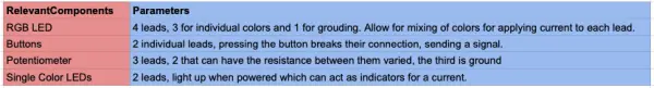
در جستجوی الهام، اتاقم را بدون هیچ ایده پروژه خاصی در ذهن کاوش کردم. در حین قدم زدن در خانه، متوجه یک چراغ شب شدم و به یاد آوردم که بسته آردوینو حاوی یک فتوسل است. این جرقه یک ایده را ایجاد کرد - من می توانم یک چراغ شب بسازم! به اندازه کافی ساده به نظر می رسید. با وجود تجربه محدود با آردوینو و سی پلاس پلاس، تصمیم گرفتم کمی خودم را به چالش بکشم. من یک نور شب را متصور بودم که با تاریکتر شدن به تدریج روشن میشود و چیزی بیش از یک عملکرد خاموش و روشن ارائه میدهد. مدار را با یک LED و فتوسل را با استفاده از circuit.io تنظیم کردم و طرح و کد آنها را تکرار کردم، اما متأسفانه آنطور که انتظار می رفت کار نکرد. در تلاش برای یافتن چگونگی انجام آن، در نهایت مجبور شدم این ایده را رها کنم.
کد نور شب
// RGB LED

// The RGB LED will appear red, green, and blue first, then red, orange, yellow, green, blue, indigo, and purple.

// Email:support@sunfounder.com

// Website:www.sunfounder.com

// 2015.5.7

/*************************************************************************/

const int redPin = 11; // R petal on RGB LED module connected to digital pin 11

const int greenPin = 10; // G petal on RGB LED module connected to digital pin 10

const int bluePin = 9; // B petal on RGB LED module connected to digital pin 9

/**************************************************************************/

void setup()

{

pinMode(redPin, OUTPUT); // sets the redPin to be an output

pinMode(greenPin, OUTPUT); // sets the greenPin to be an output

pinMode(bluePin, OUTPUT); // sets the bluePin to be an output

}

/***************************************************************************/

void loop() // run over and over again

{

// Basic colors:

color(255, 0, 0); // turn the RGB LED red

delay(1000); // delay for 1 second

color(0, 255, 0); // turn the RGB LED green

delay(1000); // delay for 1 second

color(0, 0, 255); // turn the RGB LED blue

delay(1000); // delay for 1 second

// Example blended colors:

color(255, 0, 252); // turn the RGB LED red

delay(1000); // delay for 1 second

color(237, 109, 0); // turn the RGB LED orange

delay(1000); // delay for 1 second

color(255, 215, 0); // turn the RGB LED yellow

delay(1000); // delay for 1 second

color(34, 139, 34); // turn the RGB LED green

delay(1000); // delay for 1 second

color(0, 112, 255); // turn the RGB LED blue

delay(1000); // delay for 1 second

color(0, 46, 90); // turn the RGB LED indigo

delay(1000); // delay for 1 second

color(128, 0, 128); // turn the RGB LED purple

delay(1000); // delay for 1 second

}

/******************************************************/

void color (unsigned char red, unsigned char green, unsigned char blue)// the color generating function

{

analogWrite(redPin, red);

analogWrite(greenPin, green);

analogWrite(bluePin, blue);

}

/******************************************************/

//Controlling LED by potentiometer

//Rotate the shaft of the potentiometer and you should see the luminance of the LED change.

//Email:support@sunfounder.com

//Website:www.sunfounder.com

//2015.5.7

/******************************************/

const int analogPin = 0;//the analog input pin attach to

const int ledPin = 8;//the led attach to

int inputValue = 0;//variable to store the value coming from sensor

int outputValue = 0;//variable to store the output value

/******************************************/

Serial.begin(9600);//set the serial communication baudrate as 9600

}

/******************************************/

void loop()

{

inputValue = analogRead(analogPin);//read the value from the potentiometer

Serial.print(“Input: “); //print “Input”

Serial.println(inputValue); //print inputValue

outputValue = map(inputValue, 0, 1023, 0, 255); //Convert from 0-1023 proportional to the number of a number of from 0 to 255

Serial.print(“Output: “); //print “Output”

Serial.println(outputValue); //print outputValue

analogWrite(ledPin, outputValue); //turn the LED on depending on the output value

delay(1000);

}

/*******************************************/
در عوض، من تصمیم گرفتم یک سیستم روشنایی متشکل از سه LED رنگ متفاوت ایجاد کنم که هر کدام با دکمه های جداگانه قابل کنترل هستند. به دنبال طرحبندی و کدهایی که در circuit.io پیدا کردم، دکمهها را با موفقیت وصل کردم و آنها همانطور که در نظر گرفته شده بود کار کردند. با این حال، فکر میکردم اگر بتوانم تمام نور را تنها با یک دکمه کنترل کنم، حتی خنکتر میشود، بنابراین تصمیم گرفتم روی آن جنبه کار کنم.
سفر به سمت محصول نهایی:
برای آشنایی با روشن کردن LED RGB، گام اولیه من شامل دانلود کدی از انجمن آردوینو بود. این کد طوری برنامه ریزی شده بود که در میان رنگ های مختلف، از جمله ترکیب رنگ های مختلف برای ایجاد رنگ های جدید، چرخش کند. با تجزیه و تحلیل کد، مفهوم تخصیص مقادیر به رنگ های مختلف را درک کردم، مهارتی حیاتی که برای پروژه خودم مفید است.

کد برای رنگ های دوچرخه سواری LED RGB.
//RGB LED
//The RGB LED will appear red, green, and blue first, then red, orange, yellow, green, blue, indigo, and purple.
//Email:support@sunfounder.com
//Website:www.sunfounder.com
//2015.5.7
/*************************************************************************/
const int redPin = 11; // R petal on RGB LED module connected to digital pin 11
const int greenPin = 10; // G petal on RGB LED module connected to digital pin 10
const int bluePin = 9; // B petal on RGB LED module connected to digital pin 9
/**************************************************************************/
void setup()
{
pinMode(redPin, OUTPUT); // sets the redPin to be an output
pinMode(greenPin, OUTPUT); // sets the greenPin to be an output
pinMode(bluePin, OUTPUT); // sets the bluePin to be an output
}
/***************************************************************************/
void loop() // run over and over again
{
// Basic colors:
color(255, 0, 0); // turn the RGB LED red
delay(1000); // delay for 1 second
color(0,255, 0); // turn the RGB LED green
delay(1000); // delay for 1 second
color(0, 0, 255); // turn the RGB LED blue
delay(1000); // delay for 1 second
// Example blended colors:
color(255,0,252); // turn the RGB LED red
delay(1000); // delay for 1 second
color(237,109,0); // turn the RGB LED orange
delay(1000); // delay for 1 second
color(255,215,0); // turn the RGB LED yellow
delay(1000); // delay for 1 second
color(34,139,34); // turn the RGB LED green
delay(1000); // delay for 1 second
color(0,112,255); // turn the RGB LED blue
delay(1000); // delay for 1 second
color(0,46,90); // turn the RGB LED indigo
delay(1000); // delay for 1 second
color(128,0,128); // turn the RGB LED purple
delay(1000); // delay for 1 second
}
/******************************************************/
void color (unsigned char red, unsigned char green, unsigned char blue)// the color generating function
{
analogWrite(redPin, red);
analogWrite(greenPin, green);
analogWrite(bluePin, blue);
}
/******************************************************/
//Controlling led by potentiometer
//Rotate the shaft of the potentiometer and you should see the luminance of the LED change.
//Email:support@sunfounder.com
//Website:www.sunfounder.com
//2015.5.7
/******************************************/
const int analogPin = 0;//the analog input pin attach to
const int ledPin = 8;//the led attach to
int inputValue = 0;//variable to store the value coming from sensor
int outputValue = 0;//variable to store the output value
/******************************************/
Serial.begin(9600);//set the serial communication baudrate as 9600
}
/******************************************/
void loop()
{
inputValue = analogRead(analogPin);//read the value from the potentiometer
Serial.print(“Input: “); //print “Input”
Serial.println(inputValue); //print inputValue
outputValue = map(inputValue, 0, 1023, 0, 255); //Convert from 0-1023 proportional to the number of a number of from 0 to 255
Serial.print(“Output: “); //print “Output”
Serial.println(outputValue); //print outputValue
analogWrite(ledPin, outputValue); //turn the LED on depending on the output value
delay(1000);
}
/*******************************************/
با استفاده از اصول دکمه های اساسی که از صفحه انجمن آردوینو آموختم، با موفقیت اتصالات 3 دکمه را به همان RGB LED برقرار کردم. هر دکمه با فشار دادن، LED را با یکی از سه رنگ روشن می کند. جالب اینجاست که اگر چند دکمه به طور همزمان فشار داده می شد، LED ترکیبی از رنگ های مربوطه را نمایش می داد.

RGB LED Hold برای کد رنگ
// RGB LED

// The RGB LED will appear red, green, and blue first, then red, orange, yellow, green, blue, indigo, and purple.

// Email:support@sunfounder.com

// Website:www.sunfounder.com

// 2015.5.7

/*************************************************************************/

const int redLED = 11; // R petal on RGB LED module connected to digital pin 11

const int greenLED = 10; // G petal on RGB LED module connected to digital pin 10

const int blueLED = 9; // B petal on RGB LED module connected to digital pin 9

/**************************************************************************/

// constants won’t change. They’re used here to set pin numbers:
const int redbuttonPin = 2; // the number of the RED pushbutton pin
const int greenbuttonPin = 4;
const int bluebuttonPin = 7;

// variables will change:
int redbuttonState = 0; // variable for reading the RED pushbutton status
int greenbuttonState = 0;
int bluebuttonState = 0;

void setup()

{

pinMode(redLED, OUTPUT); // sets the redPin to be an output

pinMode(greenLED, OUTPUT); // sets the greenPin to be an output

pinMode(blueLED, OUTPUT); // sets the bluePin to be an output

}

/***************************************************************************/

void loop() {
// read the state of the pushbutton value:
redbuttonState = digitalRead(redbuttonPin);
greenbuttonState = digitalRead(greenbuttonPin);
bluebuttonState = digitalRead(bluebuttonPin);

// check if the red pushbutton is pressed. If it is, the buttonState is HIGH:
if (redbuttonState == HIGH) {
// turn LED on:
digitalWrite(redPin, HIGH);
} else {
// turn LED off:
digitalWrite(redPin, LOW);
}

// check if the green pushbutton is pressed. If it is, the buttonState is HIGH:
if (greenbuttonState == HIGH) {
// turn LED on:
digitalWrite(greenPin, HIGH);
} else {
// turn LED off:
digitalWrite(greenPin, LOW);
}

// check if the green pushbutton is pressed. If it is, the buttonState is HIGH:
if (bluebuttonState == HIGH) {
// turn LED on:
digitalWrite(bluePin, HIGH);
} else {
// turn LED off:
digitalWrite(bluePin, LOW);
}

}
/******************************************************/

void color (unsigned char red, unsigned char green, unsigned char blue)// the color generating function

{

analogWrite(redLED, red);

analogWrite(greenLED, green);

analogWrite(blueLED, blue);

}

/******************************************************/
من تصمیم گرفتم که هر رنگ را با یک بار فشار دادن دکمهها روشن و خاموش کنم، نه اینکه دکمهها را نگه دارم. با استفاده از دانش عمومی قبلیام درباره پایتون، تحقیقات نحوی انجام دادم و از یکی از هم خانههایم که در رشته CS تحصیل کرده بود کمک گرفتم. با هم حلقه های if لازم برای دستیابی به این قابلیت را نوشتیم. در نتیجه، رنگهای LED هنوز هم میتوانستند مخلوط شوند، اما دیگر نیازی به نگه داشتن چند دکمه برای مشاهده ترکیب وجود نداشت. متأسفانه ویدیوی نمایش این نسخه به طور تصادفی حذف شد. با این وجود، میتوانید ویدیوی قبلی را تصور کنید و بفهمید که من اکنون میتوانم انگشتم را از دکمهها جدا کنم در حالی که چراغها روشن هستند.
من یک بار دیگر در تنظیمات خود تجدید نظر کردم و احساس کردم که تکرار قبلی کافی نیست. من می خواستم توانایی کنترل شدت هر رنگ را داشته باشم که به رنگ نهایی نهایی کمک کند. سپس، پتانسیومتر مورد استفاده در پروژه کلاس را به یاد آوردم. به نظرم رسید که بتوانم از آن برای تنظیم مستقل شدت هر رنگ استفاده کنم.
در ابتدا، من قصد داشتم پتانسیومتر را در مدار ادغام کنم و خروجی آن را به هر لید (قرمز، سبز و آبی) وصل کنم. با این حال، به زودی متوجه شدم که این رویکرد آنطور که در نظر گرفته شده بود کار نمی کند، زیرا مقاومت را به طور مساوی در تمام سرنخ ها توزیع می کند و همه رنگ ها را به طور همزمان تنظیم می کند و نه جداگانه. برای پرداختن به این موضوع، تحقیقی در صفحه انجمن آردوینو انجام دادم و یاد گرفتم که چگونه از ورودی های آنالوگ برای اندازه گیری مقاومت پتانسیومتر و تبدیل آن به مقدار مربوطه استفاده کنم. ثابت شد که این مرحله از سیم کشی همه اجزا تا نوشتن کدهای لازم بسیار زمان بر است.
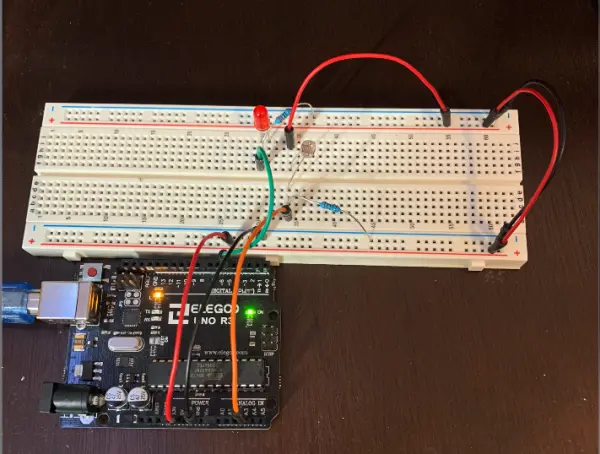
با ترکیب کدهای تکرارهای قبلی با ایده های تازه، سیستمی را با موفقیت ایجاد کردم که امکان تنظیم فردی رنگ ها را در LED RGB فراهم می کند. با نگه داشتن دکمه مربوطه، مقدار آن رنگ خاص با استفاده از پتانسیومتر قابل کنترل است. پس از رها شدن دکمه، LED مقدار تنظیم شده را حفظ می کند. برای بهبود بیشتر سیستم، تصمیم گرفتم سه LED نشانگر جداگانه را در خود جای دهم - یکی برای هر رنگ (قرمز، سبز و آبی). در نتیجه، هنگامی که دکمه مربوطه فشار داده می شود، چراغ نشانگر رنگ مربوطه روشن می شود و به کاربر در مورد رنگی که در حال تنظیم آن است اطلاع می دهد.

کد نهایی پروژه آردوینو
/*************************************************************************/

const int redLED = 11; // R petal on RGB LED module connected to digital pin 11

const int greenLED = 10; // G petal on RGB LED module connected to digital pin 10

const int blueLED = 9; // B petal on RGB LED module connected to digital pin 9

const int extraRed = 5;
const int extraGreen = 6;
const int extraBlue = 3;

/**************************************************************************/

// constants won’t change. They’re used here to set pin numbers:
const int redbuttonPin = 2; // the number of the RED pushbutton pin
const int greenbuttonPin = 4;
const int bluebuttonPin = 7;

// variables will change:
int redbuttonState = 0; // variable for reading the RED pushbutton status
int greenbuttonState = 0;
int bluebuttonState = 0;

int potPin = A3;
int potValue = 0;

int redValue = 0;
int greenValue = 0;
int blueValue = 0;

void setup()

{

pinMode(redLED, OUTPUT); // sets the redPin to be an output

pinMode(greenLED, OUTPUT); // sets the greenPin to be an output

pinMode(blueLED, OUTPUT); // sets the bluePin to be an output

pinMode(extraRed, OUTPUT); // sets the extra red LED pin
pinMode(extraGreen, OUTPUT); // green
pinMode(extraBlue, OUTPUT); // blue

}

/***************************************************************************/

void loop() {

if (digitalRead(redbuttonPin) == HIGH){ // checking if the red button is pressed
digitalWrite(extraRed, HIGH); // turning on the extra red indicator LED
redValue = (analogRead(potPin)/4); // sets the value of the red light to be equal to a fourth of the value of the potentiometer
color(redValue, greenValue, blueValue); // sets the color of the RGB LED to be the other colors’ values and the new red value
}else{
digitalWrite(extraRed, LOW); // turns off the extra red indicator LED when the button is released
}

if (digitalRead(greenbuttonPin) == HIGH){
digitalWrite(extraGreen, HIGH);
greenValue = (analogRead(potPin)/4);
color(redValue, greenValue, blueValue);
}else{
digitalWrite(extraGreen, LOW);
}

if (digitalRead(bluebuttonPin) == HIGH){
digitalWrite(extraBlue, HIGH);
blueValue = (analogRead(potPin)/4);
color(redValue, greenValue, blueValue);
}else{
digitalWrite(extraBlue, LOW);
}

}
/******************************************************/

void color (unsigned char red, unsigned char green, unsigned char blue)// the color generating function

{

analogWrite(redLED, red);

analogWrite(greenLED, green);

analogWrite(blueLED, blue);

}

/******************************************************/
من تغییراتی در قرار دادن اجزا در شماتیک Circuit.io ایجاد کردم، اما طرح کلی سیمکشی مدار را حفظ کردم.