

این پروژه در ابتدا با چند قسمت ساده در کنار هم قرار گرفتند تا یک کنترلر تایم لپس بسیار ساده برای یک دوربین DSLR ایجاد کنند. پس از اینکه از نمونه اولیه راضی بودم، میخواستم نسخه نهایی را بسازم که برنامهنویسی «زمان سپری کردن» به جای تکیه بر رایانه برای برنامهریزی مجدد و تغییر تأخیر بین جلسات عکاسی، در یک موجودیت واحد قرار میگیرد.
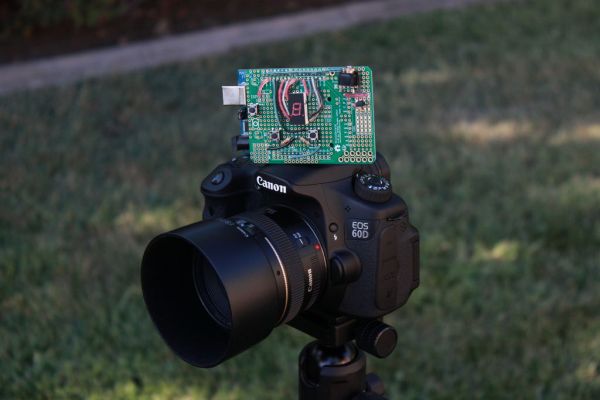
پس از افزودن یک نمایشگر، چند دکمه و یک برنامه پیچیده تر، کنترلر تایم لپس مجهز به آردوینو متولد شد!
من سعی کردم دستورالعمل ها را تا حد امکان واضح و کاربرپسند ارائه کنم، اما اگر سؤالی پیش آمد، در صورت تمایل بپرسید!
مرحله 1: قطعات
قطعات: اطلاعات: به خاطر داشته باشید که پین اوت هر نمایشگر متفاوت است و ممکن است با صفحه نمایشی که استفاده کردم (از Radioshack) متفاوت باشد، حتما به دیتاشیت آن توجه کنید. دستورالعمل ها: اطلاعات: دستورالعمل: اطلاعات: دستورالعمل ها: (توجه: مقادیر پین داده شده در این مرحله فقط به عنوان شناسه استفاده می شود و من مستقیماً با مقادیر داده شده در دیتاشیت مطابقت ندارد) اطلاعات: دستورالعمل: - مثال Blink برای جزئیات بیشتر: Arduino Time-Lapse Controller This project originally started out with a few simple parts thrown together to create a very simple time-lapse controller for a DSLR camera. After I was happy with the initial prototype, I wanted to make a final version which the programming of the “lapse time” was self contained into one single entity instead of relying on a computer to re-program and change the delay between shooting sessions. I have tried to make the instructions as clear and user-friendly as possible, but if any questions arise, feel free to ask! Parts: Info: Keep in mind that each display’s pinout is different and may differ from the display I used (from Radioshack), make sure to pay attention to its datasheet. Instructions: Info: Instructions: Info: Instructions: (NOTE: the pin values given in this step are only used as identifiers and my not directly correspond with the values given on datasheets) Info: Instructions: For more detail: Arduino Time-Lapse Controller
– آردوینو
– نمایشگر 7 بخش
– مقاومت 220 اهم x2
– مقاومت 10 کیلو اهم x2
– مقاومت 470 اهم –
سیم اتصال
– ترانزیستور NPN
– جک فونو 3/32
– سیم اتصال
– سطح نصب (یعنی پرف برد، برد برد، PCB) /box]مرحله 2: سیم کشی صفحه نمایش 7 بخش
پس از کمی تحقیق، چند کد نمونه برای نمایشگر 7 بخش در اینجا پیدا کردم . با نگاهی دقیق تر به مثال اول، متوجه شدم که هر بخش از صفحه نمایش باید به یک پین متوالی در آردوینو متصل شود. در مورد مثال، پین های 2-9 با پین 2 که "نقطه" روی نمایشگر است.
- هر دو پایه GND نمایشگر را با یک مقاومت 220 اهم به GND در آردوینو متصل کنید
- پین های نمایشگر را به پین های متوالی آردوینو وصل کنید. در مورد من از پین های 3-9 استفاده کردم
- پین نقطه را به آردوینو وصل کنید. برای من پین 2مرحله 3: سیم کشی دکمه ها
با استفاده از این به عنوان مرجع، دو دکمه را سیم کشی کردم
تصاویر موجود در لینک بالا و یکی از ضمیمه شده را دنبال کنید و فهمیدن آن باید بسیار آسان باشد.
– با استفاده از مقاومت های 10K اهم و سیم اتصال دکمه ها را به پایه های 11 و 12 وصل کردم.مرحله 4: سیم کشی کنترل شاتر
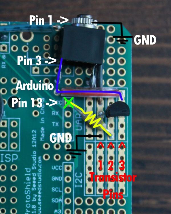
پس از خواندن دستورالعملهای ریکادم در زمان گذر، مدارم را بر اساس طرح او قرار دادم .
یک دوربین DSLR از جک phono 2/32 برای ارتباط با این مدار استفاده می کند، اما می توان آن را به راحتی با تقریباً هر دوربینی سازگار کرد.
- سیم پایه 1 جک فونو به آردونیو GND
- سیم پایه ترانزیستور NPN 1 به آردوینو GND
- سیم مقاومت 470 اهم از یک پایه آردوینو باز (در مورد من 13) به پایه ترانزیستور NPN 2
- پایه سیم 3 از جک phono به پایه 3 ترانزیستور NPNمرحله 5: Blink را آپلود کنید و یک صفحه مرجع ایجاد کنید
فرض من این است که نمایشگری که استفاده کردم و نحوه سیم کشی آن در مقایسه با پروژه شما متفاوت است. برای اطمینان از اجرای صحیح کد نهایی، باید چند مقدار را در برنامه تغییر دهیم. برای سهولت این فرآیند، یک برگه مرجع ساخته خواهد شد.
آردوینو را باز کنید و مقدار "led" را به یکی از پین های سگمنت خود تغییر دهید. طرح را دانلود و در آردوینو اجرا کنید. - مقدار "led" را دوباره به پین دیگری تغییر دهید، دانلود کنید و اجرا کنید - این روند را همزمان با مستند کردن مکان روی صفحه نمایش که هر پین روشن می شود ادامه دهید. به عنوان نمونه به تصویر اشاره کنید. در ادامه، متن انگلیسی این مطلب را میتوانید مشاهده نمایید:
After adding in a display, a couple of buttons, and a more complex program, the self contained Arduino powered Time-Lapse Controller was born!Step 1: Parts
– Arduino
– 7 Segment Display
– 220 Ohm Resistor x2
– 10K Ohm Resistor x2
– 470 Ohm Resistor
– Hookup wire
– NPN Transistor
– 3/32 Phono-jack
– hookup wire
– mounting surface (i.e. perfboard, breadboard, PCB) Step 2: Wiring up the 7 Segment Display
After a bit of research, I found some sample code for a 7 segment display here. Taking a closer look at the first example, I noticed that each segment of the display need to be wired to a sequential pin on the Arduino. In the case of the example, pins 2-9 with pin 2 being the “dot” on the display.
– Wire both GND pins of the display to GND on the Arduino with a 220 Ohm resistors
– Wire the display pins to sequential Arduino pins. In my case I used pins 3-9
– Wire the “dot” pin to the Arduino. For me, pin 2Step 3: Wiring up the Buttons
Using this as a reference, I wired up the two buttons
Follow the pictures in the above link and the one enclosed and it should be pretty easy to figure out.
– using 10K Ohm resistors and hookup wire I connected the buttons to pins 11 and 12.Step 4: Wiring up Shutter Control
After reading through rickadam’s instructable on time lapse, I based my circuit off of his design.
A DSLR camera uses a 2/32 phono-jack to interface with this circuit, but this could easily be adapted to just about any camera
– Wire pin 1 of the phono-jack to Ardunio GND
– Wire the NPN transistor pin 1 to Arduino GND
– Wire 470 Ohm resistor from an open Arduino pin (in my case 13) to NPN transistor pin 2
– Wire pin 3 of phono-jack to pin 3 of the NPN transistorStep 5: Upload Blink and Create a Reference Sheet
My assumption is that the display I used and how it is wired up is different in comparison to your project. To make sure the final code runs properly, we need to change a few values within the program. To make that process easier, a reference sheet will be made.
– Open up Arduino’s Blink example and change the value of “led” to one of your segment pins. Download and run the sketch to the Arduino.
– Change the value of “led” again to another pin, download and run
– Continue this process while documenting the location on the display each pin lights up. Reference the picture as an example.
