

PWM یا مدولاسیون عرض پالس یک روش بسیار متداول است که برای کنترل توان بین دستگاههایی مانند موتور، نور و غیره استفاده میشود. در روش PWM توان در سراسر بار با تغییر چرخه وظیفه سیگنال درایو کنترل میشود. هرچه چرخه کار، توان بیشتری در سرتاسر بار تحویل داده شود و چرخه کاری کمتر، توان کمتری در سراسر بار تحویل داده می شود. برای کنترل سرعت از صفحه کلید هگز استفاده می شود. با استفاده از صفحه کلید هگز سرعت را می توان در هفت مرحله تغییر داد. Arduino UNO نوع برد توسعه آردوینو os است که در این مدار استفاده می شود. نمودار مدار کنترل سرعت موتور PWM با استفاده از آردوینو در شکل زیر نشان داده شده است.
مدار.
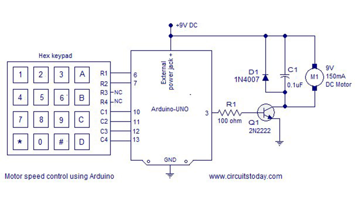
پین های ردیف R1 و R2 صفحه کلید هگز به پین های دیجیتال 6 و 7 آردوینو متصل می شوند. پایه های ستون C1، C2، C3 و C4 به پایه دیجیتال 10، 11، 12 و 13 آردوینو متصل هستند. کلید فشار داده شده روی صفحه کلید هگز با استفاده از روش اسکن ستونی شناسایی شده و در این مقاله به تفصیل توضیح داده شده است. رابط صفحه کلید هگزا با آردوینو . پینهای دیجیتال آردوینو میتوانند تنها تا 4 میلی آمپر جریان را منبع یا کاهش دهند. بنابراین پین دیجیتال 3 نمی تواند مستقیماً موتور را هدایت کند. برای حل این مشکل از یک ترانزیستور NPN (2N2222) برای به حرکت درآوردن موتور بر اساس سیگنال PWM موجود در پایه دیجیتال 3 استفاده می شود. مقاومت 100 اهم R1 برای محدود کردن جریان پایه ترانزیستور استفاده می شود. موتور به عنوان بار کلکتور به ترانزیستور متصل می شود. خازن C1 0.1uF متصل به موتور برای دور زدن نویزهای ولتاژ و نویزهای تولید شده در هنگام تعویض موتور استفاده می شود.
تغذیه برد آردوینو از طریق جک پاور خارجی موجود بر روی برد تامین می شود. برد آردوینو می تواند توسط کامپیوتر از طریق USB نیز تغذیه شود، اما باید یک منبع خارجی اضافی برای تغذیه موتور وجود داشته باشد. برنامه کامل کنترل سرعت موتور PWM با استفاده از آردوینو در زیر آورده شده است. توضیح برنامه تحت عنوان "درباره برنامه" آورده شده است.
بیشتر بخوانید: کنترل سرعت موتور PWM با استفاده از آردوینو
در ادامه، متن انگلیسی این مطلب را میتوانید مشاهده نمایید:
PWM or pulse width modulation is a very common method used for controlling the power across devices like motor, light etc. In PWM method the power across the load is controlled by varying the duty cycle of the drive signal. More the duty cycle more power is delivered across the load and less the duty cycle, less power is delivered across the load. A hex keypad is used for controlling the speed. The speed can be varied in seven steps using the hex keypad. Arduino UNO is the type os arduino development board used in this circuit. The circuit diagram of the PWM motor speed control using arduino is shown in the figure below.
Circuit diagram.
Row pins R1 and R2 of the hex keypad are interfaced to digital pins 6 and 7 of the arduino. Column pins C1, C2, C3 and C4 are interfaced to the digital pind 10, 11, 12 and 13 of the arduino. The key pressed on the hex keypad is identified using the column scanning method and it is explained in detail in this article. Interfacing hex keypad to arduino. The digital pins of the arduino can source or sink only up to 4omA of current. So the digital pin 3 cannot drive the motor directly. To solve this problem an NPN transistor (2N2222) is used to drive the motor according the the PWM signal available at digital pin 3. 100 ohm resistor R1 is used to limit the base current of the transistor. The motor is connected as a collector load to the transistor. The 0.1uF capacitor C1 connected across the motor is used to by-pass the voltage spikes and noises produced during the switching of the motor.
The arduino board is powered through the external power jack provided on the board. The arduino board can be also powered by the PC through USB but there must be an additional external source for powering the motor. The complete program for PWM motor speed control using arduino is given below. Explanation of the program is given under the “About the program” heading.
Read More: PWM motor speed control using Arduino
