

این پست راهنمای افرادی است که به پست های قبلی من در مورد هک VGA با مانیتور دوگانه علاقه مند هستند (به 1 ، 2 و 3 مراجعه کنید ).
شما نیاز دارید:
• یک لپ تاپ یا یک کامپیوتر با خروجی VGA
• یک تخته نان (اختیاری) و تعدادی سیم یا یک تخته نواری برای لحیم کاری
• بلوزهای سیم و تخته نان (اختیاری)
• 2 کانکتور VGA ماده
• 1 کانکتور VGA نر
• حداکثر 3 تعداد زیادی هدر پین 15×1 یا 15×2 (اختیاری)
• یک میکروکنترلر Arduino، Picaxe یا سایر میکروکنترلرها با ADC داخلی یا ADC مستقل
• کابل و کانکتور صدا
• 1 یا 2 مانیتور CRT یا LCD
راه اندازی سخت افزار:
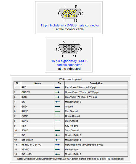
ایده در اینجا اتصال سیگنال های همگام افقی و عمودی از رایانه / لپ تاپ به مانیتورهای دیگر است. با این حال، خطوط داده واقعی RGB توسط Arduino / μC / ADC کنترل می شود. میتوانید پینآوتهای پورتهای VGA را در زیر ببینید (برگرفته از pinouts.ru ).
بنابراین، برخی از کانکتورها را یا لحیم کنید یا تخته نان!
از خروجی VGA کامپیوتر / لپ تاپ تا اولین مانیتور خارجی، پین های
4، 5، 6، 7، 8، 10، 11، 12، 13 و 14 را وصل کنید.
از اولین مانیتور خارجی به مانیتور خارجی دوم، پایه های
5، 6، 7، 8، 13 و 14 را وصل کنید. سپس پایه 1 اولین مانیتور خارجی را به پایه 2 مانیتور خارجی دوم، پایه 3 را به پایه 2 وصل کنید. پین 2 به پین 3. با تغییر این نگاشت می توانید رنگ مانیتور دوم را نسبت به اولی تغییر دهید.
برای راه اندازی، از برد آردوینو استفاده کردم. بنابراین من یک سیگنال صوتی گرفتم و سیم سیگنال را به پایه آنالوگ 0 و شیلد را به زمین آردوینو وصل کردم. من همچنین زمین آردوینو را به پایه 5 کانکتورهای VGA وصل کردم. سپس پایه های 4 و 5 و 6 آردوینو را به پایه های 1 و 2 و 3 اولین اتصال مانیتور خارجی وصل کردم.
همچنین، برای راه اندازی، من اساساً سه تخته جامپر کوچک با هدرهای پین ساختم که همه پانزده پین VGA را به برد برد متصل می کند. سپس استفاده از جامپرهای تخته نان برای اتصال هر پین مناسب به دیگری - آسان بود!
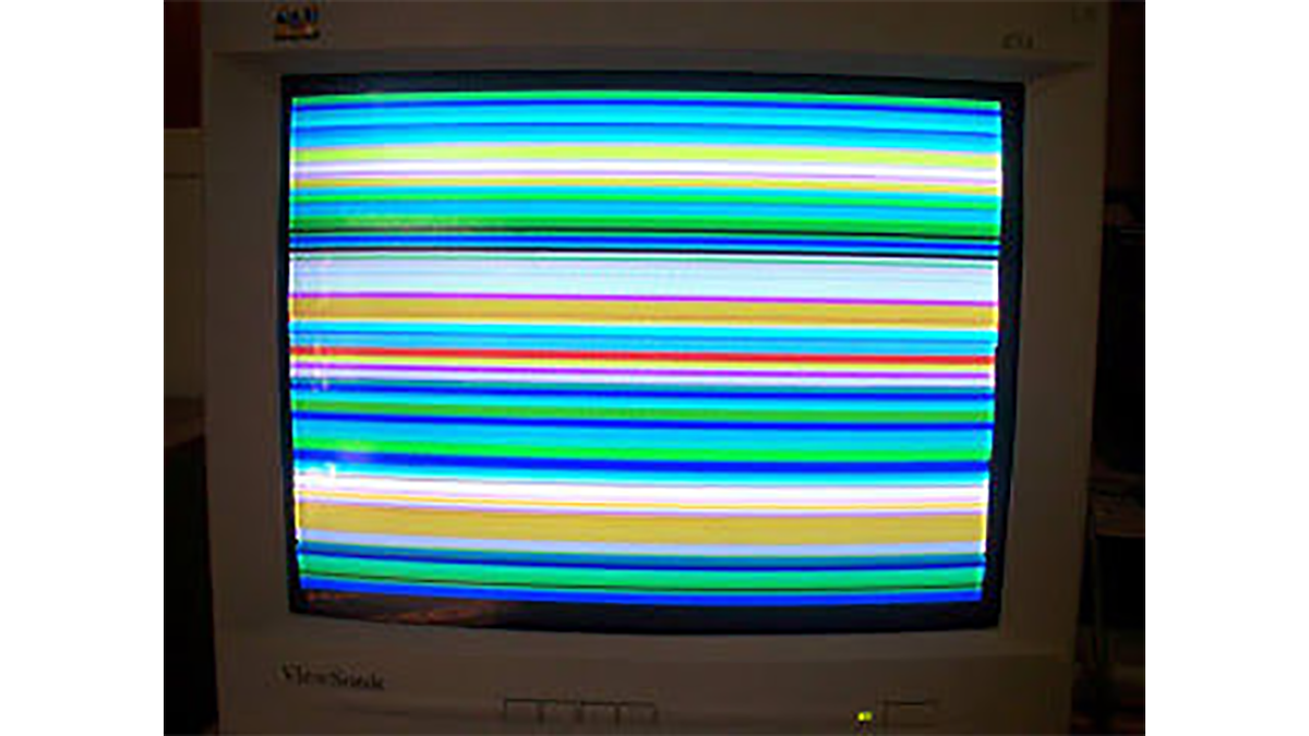
برای جزئیات بیشتر: چگونه: از Arduino برای تولید تصاویر VGA صوتی Glitchy استفاده کنید
در ادامه، متن انگلیسی این مطلب را میتوانید مشاهده نمایید:
This post is a guide for people that are interested in my previous posts about dual monitor VGA hacking (see 1, 2 and 3).
You will need:
• A laptop or a computer with a VGA output
• A breadboard (optional) and some wires or a strip board for soldering
• Wire and breadboard jumpers (optional)
• 2 female VGA connectors
• 1 male VGA connector
• up to 3 lots of 15×1 or 15×2 pin headers (optional)
• An Arduino, Picaxe or other microcontroller with an onboard ADC or a standalone ADC
• Audio cable and connector
• 1 or 2 CRT or LCD monitors
Hardware Setup:
The idea here is to connect the horizontal and vertical sync signals from the computer / laptop to the other monitors. However, the actual RGB data lines will be controlled by the Arduino / µC / ADC. You can see the pinouts for the VGA ports below (taken from pinouts.ru).
So, either solder or breadboard up some connectors!
From the VGA output of the computer / laptop to the first external monitor, connect pins:
4, 5, 6, 7, 8, 10, 11, 12, 13 and 14.
From the first external monitor to the second external monitor, connect pins:
5, 6, 7, 8, 13 and 14. Then connect pin 1 of the first external monitor to pin 2 of the second external monitor, pin 3 to pin 2 and pin 2 to pin 3. By changing this mapping, you can change the way the colour of the second monitor looks like compared to the first one.
For my setup, I used an Arduino board. So I took an audio signal and connected the signal wire to analog pin 0 and the shield to Arduino ground. I also connected Arduino ground to pin 5 of the VGA connectors. Then I connected Arduino pins 4, 5 and 6 to pins 1, 2 and 3 of the first external monitor connection.
Also, for my setup, I basically made up three little jumper boards with pin headers that connect all fifteen VGA pins to the breadboard. Then it was simply a matter of using breadboard jumpers to connect each appropriate pin to the other – easy!
For more detail: How to: Use Arduino to Generate Glitchy Audio VGA Visuals
