

ما یک آموزش برای رمزگذارهای روتاری با استفاده از میکروکنترلر میکروچیپ نوشتهایم، اما اکنون زمان خوبی برای ساخت نسخه Arduino UNO است.
با یک انکودر چرخشی دو خروجی موج مربعی (A و B) داریم که 90 درجه با یکدیگر خارج از فاز هستند. تعداد پالس ها یا مراحل تولید شده در هر نوبت کامل متفاوت است. رمزگذار روتاری Sparkfun دارای 12 مرحله است اما سایرین ممکن است بیشتر یا کمتر داشته باشند. نمودار زیر نشان می دهد که چگونه فازهای A و B به یکدیگر مربوط می شوند وقتی که رمزگذار در جهت عقربه های ساعت یا خلاف جهت عقربه های ساعت چرخانده می شود.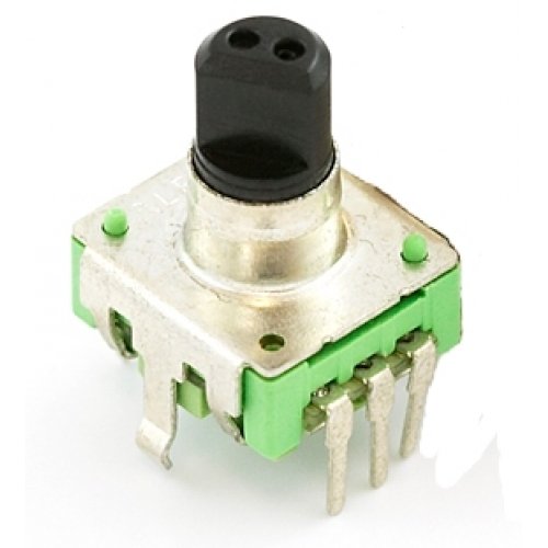
هر بار که پالس سیگنال A از مثبت به صفر می رسد، مقدار پالس B را می خوانیم. می بینیم که وقتی رمزگذار در جهت عقربه های ساعت می چرخد، پالس B همیشه مثبت است. هنگامی که رمزگذار در خلاف جهت عقربه های ساعت چرخانده می شود، پالس B منفی است. با آزمایش هر دو خروجی با میکروکنترلر، میتوان جهت چرخش را تعیین کرد و تعداد پالسهای A را تا چه اندازه دور زده است. در واقع، ما میتوانیم یک مرحله جلوتر برویم و فرکانس پالسها را بشماریم تا مشخص کنیم با چه سرعتی در حال چرخش است. می بینیم که رمزگذار چرخشی مزایای زیادی نسبت به پتانسیومتر دارد.
ما اکنون از رمزگذار چرخشی در ساده ترین برنامه ها استفاده خواهیم کرد، ما از آن برای کنترل روشنایی یک led با تغییر سیگنال pwm استفاده خواهیم کرد. ما از ساده ترین روش برای خواندن رمزگذار استفاده خواهیم کرد، یعنی استفاده از وقفه تایمر برای بررسی مقادیر.
همانطور که در بالا توضیح داده شد از رمزگذار sparkfun استفاده خواهیم کرد. اولین چیز این است که تعیین کنیم با چه سرعتی به تایمر خود نیاز داریم تا کار کند. اگر تصور کنید که در بهترین حالت میتوانیم رمزگذار را 180 درجه در 1/10 ثانیه بچرخانیم، 6 پالس در 1/10 ثانیه یا 60 پالس در ثانیه به ما میدهد. در واقع هرگز به این سرعت نمی تواند باشد. از آنجایی که ما باید هم مقادیر بالا و هم مقادیر پایین را تشخیص دهیم، این حداقل فرکانس 120 هرتز را به ما می دهد. برای اطمینان به سراغ 200 هرتز برویم. (توجه: از آنجایی که این واحدها سوئیچ های مکانیکی هستند، امکان جهش سوئیچ وجود دارد. استفاده از فرکانس نسبتاً پایین به ما امکان می دهد تا به طور موثر هرگونه جهش سوئیچ را فیلتر کنیم)
هر بار که کد تایمر ما فعال می شود، مقدار پالس A خود را با مقدار قبلی آن مقایسه می کنیم. اگر از مثبت به صفر رسیده است، مقدار پالس B را بررسی می کنیم تا ببینیم مثبت است یا صفر. بسته به نتیجه، می توانیم یک شمارنده را کاهش دهیم. سپس از این برای کنترل مقدار PWM برای افزایش یا کاهش روشنایی LED استفاده می کنیم
و کد منبع طرح در زیر نشان داده شده است. این بر اساس آموزش قبلی است که در آن از تابع millis () برای ارائه یک بازه زمانی استفاده کردیم. ما در اینجا از همان ایده استفاده می کنیم اما از 5 میلی ثانیه به عنوان بررسی زمان سپری شده (5 میلی ثانیه = 200 هرتز) استفاده می کنیم. امیدواریم، کد باید به اندازه کافی آسان برای درک باشد و به راحتی قابل تغییر باشد تا رمزگذار روتاری را برای استفاده های دیگر قرار دهد.
برای جزئیات بیشتر: Arduino UNO Tutorial 6 – Rotary Encoder
در ادامه، متن انگلیسی این مطلب را میتوانید مشاهده نمایید:
We have written a tutorial for Rotary Encoders using a Microchip microcontroller but now would be a good time to make an Arduino UNO version.
With a rotary encoder we have two square wave outputs (A and B) which are 90 degrees out of phase with each other. The number of pulses or steps generated per complete turn varies. The Sparkfun Rotary Encoder has 12 steps but others may have more or less. The diagram below shows how the phases A and B relate to each other when the encoder is turned clockwise or counter clockwise.
Every time the A signal pulse goes from positive to zero, we read the value of the B pulse. We see that when the encoder is turned clockwise the B pulse is always positive. When the encoder is turned counter-clockwise the B pulse is negative. By testing both outputs with a microcontroller we can determine the direction of turn and by counting the number of A pulses how far it has turned. Indeed, we could go one stage further and count the frequency of the pulses to determine how fast it is being turned. We can see that the rotary encoder has a lot of advantages over a potentiometer.
We will now use the rotary encoder in the simplest of applications, we will use it to control the brightness of an led by altering a pwm signal. We will use the easiest method to read the encoder, that is the use of a timer interrupt to check on the values.
We will use the sparkfun encoder as discussed above. The first thing is to determine how fast we need our timer to operate. If you imagine that at best we could turn the encoder through 180 degrees in 1/10th of a second, that would give us 6 pulses in 1/10th second or 60 pulse per second. In reality its never likely to be this fast. As we need to detect both high and low values this gives us a minimum frequency of 120Hz. Lets go for 200Hz just to be sure. (Note: as these units are mechanical switches, there is the possibility of switch bounce. Using a fairly low frequency allows us to effectively filter out any switch bounce)
Each time our timer code triggers, we compare the value of our A pulse with its previous value. If it has gone from positive to zero, we then check the value of the B pulse to see if it is positive or zero. Depending on the outcome we can increment of decrement a counter. We then use this to control the PWM value to increase or decrease the brightness of the LED
And the source code for the sketch is shown below. It builds on the previous tutorial where we used the millis() function to give us a timing interval. We use the same idea here but use 5ms as the elapsed time check (5ms = 200Hz). Hopefully, the code should be easy enough to understand and easily modifyable to put the Rotary Encoder to other uses.
For more detail: Arduino UNO Tutorial 6 – Rotary Encoder
