

برای یک کلاس، من و هم تیمی ام تصمیم گرفتیم یک سیستم مبتنی بر MIDI ایجاد کنیم که دارای یک نور پاسخگو برای هر نت پخش شود. برای مثال، اگر تنظیمات کوچک ما را به صفحهکلید متصل کنید، با توجه به اینکه کدام یادداشت را فشار میدهید، رنگ خاصی دریافت خواهید کرد. شما به لیستی از چندین مورد نیاز دارید، اما پاداش آن بسیار خوب است! بهعلاوه، بسیاری از پیشرفتها و پیشرفتهای احتمالی از ایده اصلی وجود دارد، بنابراین لطفاً وقتی همه چیز را کنار هم گذاشتید، این مفهوم را گسترش دهید.
مرحله 2: همه چیز را در کنار هم قرار دهید
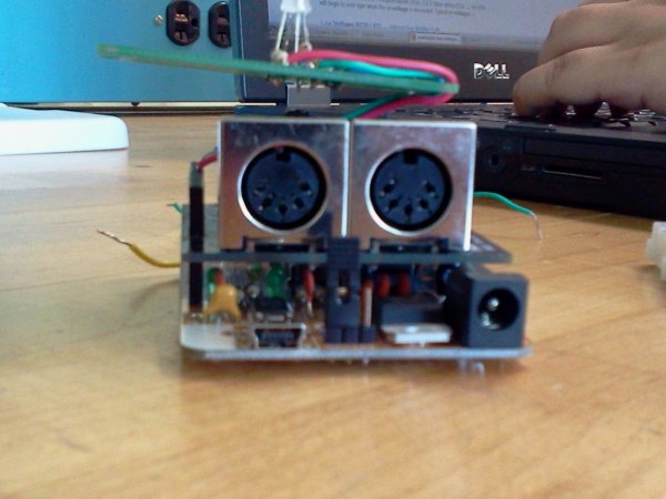
فرمت اصلی این شماتیک این است که هر پایه LED به یک پایه متفاوت در Midi Shield متصل می شود. به ولتاژ پایین پایه قرمز LED ما توجه کنید. کاتد به زمین می رود. سپر midi در بالای آردوینو متصل می شود، به همین دلیل است که هدرهای توسعه یافته برای عملکرد چراغ های ما ضروری است. این یک ساخت بسیار ساده و سرراست است، اما فضای زیادی را برای گسترش نیز فراهم می کند.
مرحله 3: مفاهیم Midi…
برای برنامه نویسی با Midi، باید چند مفهوم کلیدی را درک کنید که نحوه خواندن اطلاعات را تعیین می کند.
Midi اطلاعات را با 3 بایت اطلاعات با نرخ باود 31250 ارسال می کند. بایت اول تعیین می کند که آیا یک نت روشن است یا خیر، بایت بعدی تعیین می کند که چه آهنگی پخش شود و بایت سوم میزان صدای نت را تعیین می کند. توجه به ترتیب اطلاعات مهم است که اگر کد را برای خواندن به این ترتیب برای تنها 3 بایت تنظیم نکنید، چیزهای خنده دار شروع به رخ دادن می کنند. به ما اعتماد کنید.

کد زیر را در نظر بگیرید:
//reads the serial port to see if there is any incoming information
boolean check_midi()
{
   while (Serial.available() >= 3)//when three bytes available
   {
     if (Serial.available())
     {
       digitalWrite(3,HIGH);
       location_byte = Serial.read();//read first byte
       in_note = Serial.read();//read next byte
       in_volume = Serial.read();//read final byte
       return true;
     }
   }
}
مرحله 1 - مواد مورد نیاز: 1 Midi Shield- DF Robot Midi Shield (http://www.dfrobot.com/index.php?route=product/product&product_id=526). این Midi Shield با هدرهای توسعه یافته عرضه نمی شد، بنابراین ما باید پین های اتصال شیلد را به آردوینو با هدرهای توسعه یافته جایگزین کنیم. این فرآیند به ابزارهای لحیم کاری و لحیم کاری نیاز دارد، بنابراین هنگام انتخاب شیلد میدی خود به این موضوع توجه کنید. 1 LED- RGB LED (4 پین) - قبل از استفاده از LED های خود اطلاعات را بررسی کنید. می توانید از یک ماشین حساب LED http://led.linear1.org/1led.wiz برای تعیین مقاومت های مناسب مورد نیاز برای مدار خود استفاده کنید. آردوینو 5 ولت تولید می کند. 1 کابل MIDI (USB به MIDI اختیاری است، بستگی به ابزار مورد استفاده با سپر MIDI شما دارد. 2 مقاومت 1kΩ (قهوه ای-سیاه-قرمز) 1 مقاومت 560Ω (سبز-آبی-قهوه ای) مقاومت های مورد استفاده به LED بستگی دارد. این مقاومت ها روشنایی ثابتی را بین هر سه رنگ ایجاد می کردند. مقاومت های 1kΩ برای پایه های آبی و سبز و مقاومت 560Ω با پایه قرمز استفاده شد. سیمها - برای سادهترین تجربه، سیمهای قرمز، سبز و آبی را برای پایههای مختلف LED و یک سیم سیاه را به عنوان زمین انتخاب کنید. تخته نان 4 هدر توسعه یافته (اختیاری) فقط در صورتی استفاده می شود که سپر Midi نیاز به اصلاح داشته باشد.آنچه شما نیاز خواهید داشت…
1 Arduino- Arduiono مورد استفاده برای این پروژه Freeduino v 1.22 بود. این از قبل مونتاژ نشده است، تا زمانی که پین ها بتوانند با تخته های استفاده شده در محافظ میانی هماهنگ شوند، می توان از تخته های دیگر استفاده کرد.
برای جزئیات بیشتر: Midi Light Show با استفاده از آردوینو
در ادامه، متن انگلیسی این مطلب را میتوانید مشاهده نمایید:
For a class, my teammate and I decided to develop a MIDI based system that has a responsive light for each note played. For example, if you plug our little setup to a keyboard, pending on which note you press, you’ll get a specific color. You’ll need a list of several items, but the reward is quite nice! Plus, there are a lot of possible improvements and developments from the original idea, so please take the liberty to expand on this concept once you’ve put everything together.
Step 2: Putting It All Together
The main format of this schematic is that each pin of the LED is connected to a different pin on the Midi Shield. note the lower voltage for the red leg of our LED. The cathode goes to ground. The midi shield connects on top of the Arduino, which is why extended headers are necessary for the function of our lights. This is an extremely simple and straightforward build, but it provides a lot of room for expansion as well.
Step 3: Midi Concepts…
To program with Midi, you must understand a few key concepts that determine how the information is read.
Midi sends information with 3 bytes of information at a baud rate of 31250. The first byte determines whether a note is turned on, the next byte determines what pitch is played, and the third byte determines the volume of the note. It is important to note the order of the information as if you don’t set the code to read in this order for only 3 bytes, funny things start happening. Trust us.
Consider the following code:
//reads the serial port to see if there is any incoming information
boolean check_midi()
{
   while (Serial.available() >= 3)//when three bytes available
   {
     if (Serial.available())
     {
       digitalWrite(3,HIGH);
       location_byte = Serial.read();//read first byte
       in_note = Serial.read();//read next byte
       in_volume = Serial.read();//read final byte
       return true;
     }
   }
}
What you’ll need…
Step 1 — Materials Needed:
1 Arduino- The Arduiono used for this project was a Freeduino v 1.22. This did not come pre-assembled, Other boards can be used, as long as the pins are able to line up with those used on the midi shield
1 Midi Shield- DF Robot Midi Shield (http://www.dfrobot.com/index.php?route=product/product&product_id=526). This Midi Shield did NOT come with extended headers, so we needed to replace the pins connecting the shield to the arduino with extended headers. This process requires desoldering and soldering tools, so consider this when choosing your midi shield.
1 LED- RGB LED (4 pins) — Check the information on your LEDs before using them. You can use an LED calculator http://led.linear1.org/1led.wiz to determine the proper resistors needed for your circuit. The Arduino produces 5 volts.
1 MIDI Cable (USB to MIDI is optional, it depends on the instrument used with your midi shield
2 1kΩ resistors (Brown-Black-Red)
1 560Ω resistor (Green-Blue-Brown)
The resistors used depends on the LED. These resistors produced a consistent brightness between all three colors. the 1kΩ resistors were used for the blue and green legs, and the 560Ω resistor was used with the red leg.
Wires — For the simplest experience, choose Red, Green, and Blue wires for the different legs of the LED, and a black wire as the ground.
Breadboard
4 Extended Headers (Optional) Only used if the Midi shield needs to be modified.
For more detail: Midi Light Show using Arduino
[/membership]