

به اندازهای کوچک که در یک قوطی نعناع لغزیده شود، در عین حال به اندازهای بلند است که در یک خانه فقط چند دلار در هر واحد شنیده شود. یک ترکیب خوب برای یک شوخی خوب! بیایید شیرجه بزنیم!
مرحله اول: مدار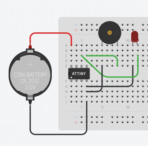
با استفاده از لینک موجود در قسمت قطعات این بیلد می توانید برد مدار چاپی را از OSH Park خریداری کنید. شما به هیچ وجه نیازی به استفاده از ATtiny یا برد مدار چاپی خودم ندارید. این مدار در مجموع حدود 20 دقیقه طول می کشد تا روی هر تخته نان بورد مونتاژ شود. با این حال، اگر می خواهید مدار کوچک باشد، من از گزینه برد مدار چاپی استفاده می کنم. اگر برد برد یا پرف برد آن برای شما جالب است، نسخه برد برد در بالا نشان داده شده است. ATtiny85 را با هر میکروکنترلر تعویض کنید.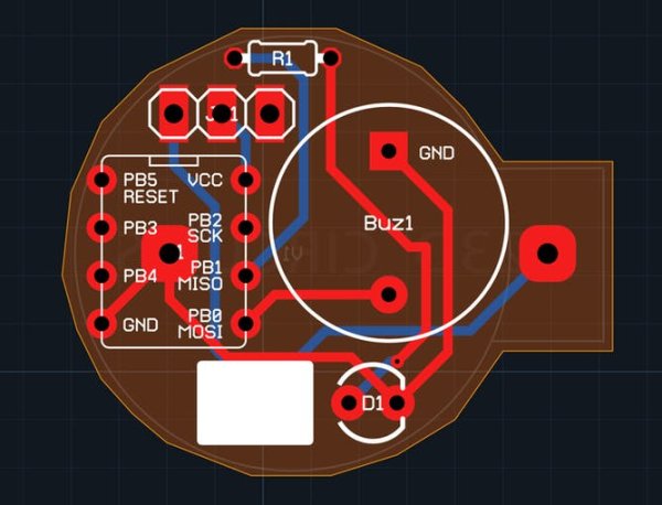
این باید یک PCB نسبتاً آسان برای پر کردن قطعات باشد. فقط به خاطر داشته باشید که آژیر و LED اجزای پلاریزه هستند . سرب بلندتر زنگ باید از صفحه گرد عبور کند و سرب کوتاهتر باید از صفحه مربع عبور کند. سرب بلندتر LED باید از سوراخ مقابل مستطیل سفید عبور کند. تنها بخش دشوار این کار، لحیم کردن کانکتور باتری است. اطمینان حاصل کنید که ابتدا تمام قطعات را در قسمت جلویی لحیم کرده اید. سپس می توانید پین زمین کانکتور باتری را از طریق سوراخ در مرکز سوکت DIP به پد آن لحیم کنید.
من همچنین یک مستطیل صفحه ابریشمی سفید را روی PCB قرار داده ام تا در صورتی که بخواهید پیام کوچکی برای شوخی خود بنویسید :). اگر میخواهید PCB را سفارشی کنید، فقط طرح circuits.io من را کپی کنید : https://circuits.io/circuits/2677013-annoying-circuit
مرحله سوم: نرم افزار
//Code produced by Alex Wulff: http://www.AlexWulff.com
#define BUZZ      0
#define LED       1
#define INITIAL   5000
//10,000 ms yields a total sequence time of 46.5 Seconds
//20,000 ms yields a total sequence time of 91.5 Seconds
//30,000 ms yields a total sequence time of 136.5 Seconds
//You get the pattern. Each 10 seconds yields another 45
//seconds of total time on the sequence.
void setup() {
 // put your setup code here, to run once:
 pinMode(BUZZ, OUTPUT);
 pinMode(LED, OUTPUT);
 //Flash the light to make sure the device is working
 for (int i = 0; i < 5; i++) {
   digitalWrite(LED, HIGH);
   delay(200);
   digitalWrite(LED, LOW);
   delay(200);
 }
}
void loop() {
 for (int i = 1; i < 50; i++) {
   digitalWrite(BUZZ, HIGH);
   digitalWrite(LED, HIGH);
   delay(30);
   digitalWrite(0, LOW);
   digitalWrite(LED, LOW);
   delay(INITIAL/i);
 }
}
در بالا نمونه برنامه کوتاهی وجود دارد که برخی از قابلیت های این دستگاه را نمایش می دهد. همچنین این برنامه در حال اجرا در ویدیو نشان داده شده در بالا است. زمان بین هر بوق بعدی به تدریج کمتر می شود، که می تواند واقعا آزار دهنده باشد! می توانید مقیاس زمانی را در این طرح با تغییر INITIAL به چیزی بسیار بزرگتر تغییر دهید. حتی ممکن است این دویدن در طول یک هفته انجام شود و هر روز به تدریج سریعتر شود!
برای جزئیات بیشتر: The Annoy-O-Bug: A Chirping Light-Up Throwie
در ادامه، متن انگلیسی این مطلب را میتوانید مشاهده نمایید:
Small enough to slip in a mint tin, yet loud enough to be heard across a house at only a few dollars per unit. A nice combination for a pretty good prank! Let’s dive in!
Step One: The Circuit
You can purchase the printed circuit board from OSH Park using the link in the parts section of this build. You by no means need to use an ATtiny or my own printed circuit board. This circuit would take a grand total of about 20 minutes to assemble on any breadboard. If you want the circuit to be tiny, however, I would go with the printed circuit board option. If breadboarding it or perfboarding it does interest you, the breadboarded version is shown above. Swap out the ATtiny85 for any microcontroller.
This should be a fairly easy PCB to populate with components. Just keep in mind that the buzzer and LED are polarized components. The buzzer’s longer lead should go through the round pad, and the shorter lead should go through the square pad. The LED’s longer lead should go through hole opposite the white rectangle. The only tricky part of this is getting the battery connector soldered. Make sure you solder all the components on the front first. You can then solder the ground pin of the battery connector to its pad through the hole in the center of the DIP socket.
I have also included a white silkscreen rectangle on the PCB in case you want to write your prankee a small message :). If you would like to customize the PCB, just duplicate my circuits.io design: https://circuits.io/circuits/2677013-annoying-circuit
Step Three: The Software
//Code produced by Alex Wulff: http://www.AlexWulff.com
#define BUZZ      0
#define LED       1
#define INITIAL   5000
//10,000 ms yields a total sequence time of 46.5 Seconds
//20,000 ms yields a total sequence time of 91.5 Seconds
//30,000 ms yields a total sequence time of 136.5 Seconds
//You get the pattern. Each 10 seconds yields another 45
//seconds of total time on the sequence.
void setup() {
 // put your setup code here, to run once:
 pinMode(BUZZ, OUTPUT);
 pinMode(LED, OUTPUT);
 //Flash the light to make sure the device is working
 for (int i = 0; i < 5; i++) {
   digitalWrite(LED, HIGH);
   delay(200);
   digitalWrite(LED, LOW);
   delay(200);
 }
}
void loop() {
 for (int i = 1; i < 50; i++) {
   digitalWrite(BUZZ, HIGH);
   digitalWrite(LED, HIGH);
   delay(30);
   digitalWrite(0, LOW);
   digitalWrite(LED, LOW);
   delay(INITIAL/i);
 }
}
Above is a short sample program that displays some of the capabilities of this device. It is also the program running in the video shown at the top. The time between each subsequent beep gets progressively smaller, which can get really annoying! You could change the time scale on this sketch by changing INITIAL to something much larger. It’s even possible to have this run over the course of a week, getting progressively faster each day!
For more detail: The Annoy-O-Bug: A Chirping Light-Up Throwie
